CROSS SECTION SOFTWARE
Cross Section Software for Earthwork Cubature from a DEM
STREAM is cross section software for earthwork engineers: it computes cut and fill quantities the way road and survey engineers do, by cross-sections. Draw an axis on the terrain, set the section interval, and STREAM slices a section out of the DEM at every station, measures each cut/fill area, and sums the volume between sections into a total.
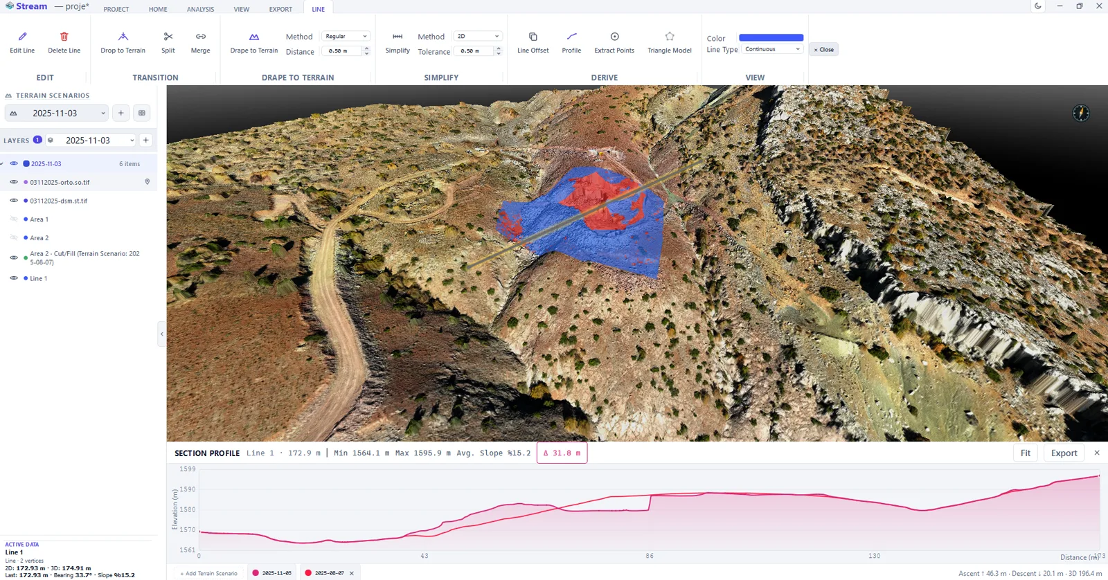
What is cross-section cubature?
Cubature is the volume of earthwork computed from cross-sections taken at regular stations along an alignment. The area of cut and fill at each section is measured, and the volume between sections is summed (average end-area).
It is the standard method for roads, canals, channels and trenches, because it produces a checkable, station-by-station quantity table.
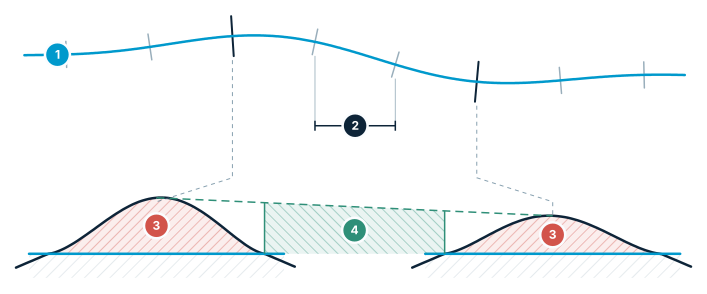
Cross-section cubature
Axis → stations → area per section → volume from areas.
- Axis — the alignment drawn on the terrain
- Station interval (L) — sections are taken at equal spacing
- Section area — cut and fill area measured at each station
- Volume between sections — summed with the average end-area method
Cross Section Software in STREAM
Sections from the DEM
Set the axis with two clicks; STREAM cuts a section from the DEM at every station, so the ground line always matches the real terrain.
Cut/fill area per station
The cut and fill area of each section is measured automatically at the interval you choose.
Cubature table
Get a clean station-by-station table of area and volume, with total cut and fill (average end-area).
DXF section drawings
Export the cross-section drawings as DXF, ready to drop into CAD.
Four ways to define the reference
Compare the ground against a 3D surface, against a flat design level you type in, against the lowest point of the area, or against a second terrain scenario. The boundary area is chosen explicitly — the first entry in the list is "none selected", so nothing is ever computed against a surface you did not pick.
The axis in two clicks
Click P1 and P2 on the terrain to set the section axis, or click an existing drawn line. While you are picking, the dialog parks at the bottom of the screen and tells you exactly what to do; a right-click cancels. The status line then reads back the coordinates it captured, so you can see what was actually used.
Interval, swell, chainage and exaggeration
Set the spacing between sections from 0.1 up, a swell factor for the fill, the starting chainage of the ruler, and a vertical exaggeration used only in the DXF drawing. A precise mode samples the sections exactly on the DEM pixel when the geometry is tight.
Cut, fill and the mass-haul curve
Three result cards give total cut, total fill and the net mass-haul figure, and the station table lists chainage, cut area, fill area, volume and cumulative mass-haul in your active unit system. Export the table to Excel or CSV and the drawings to DXF, both from the preview once the calculation has run.
In the product
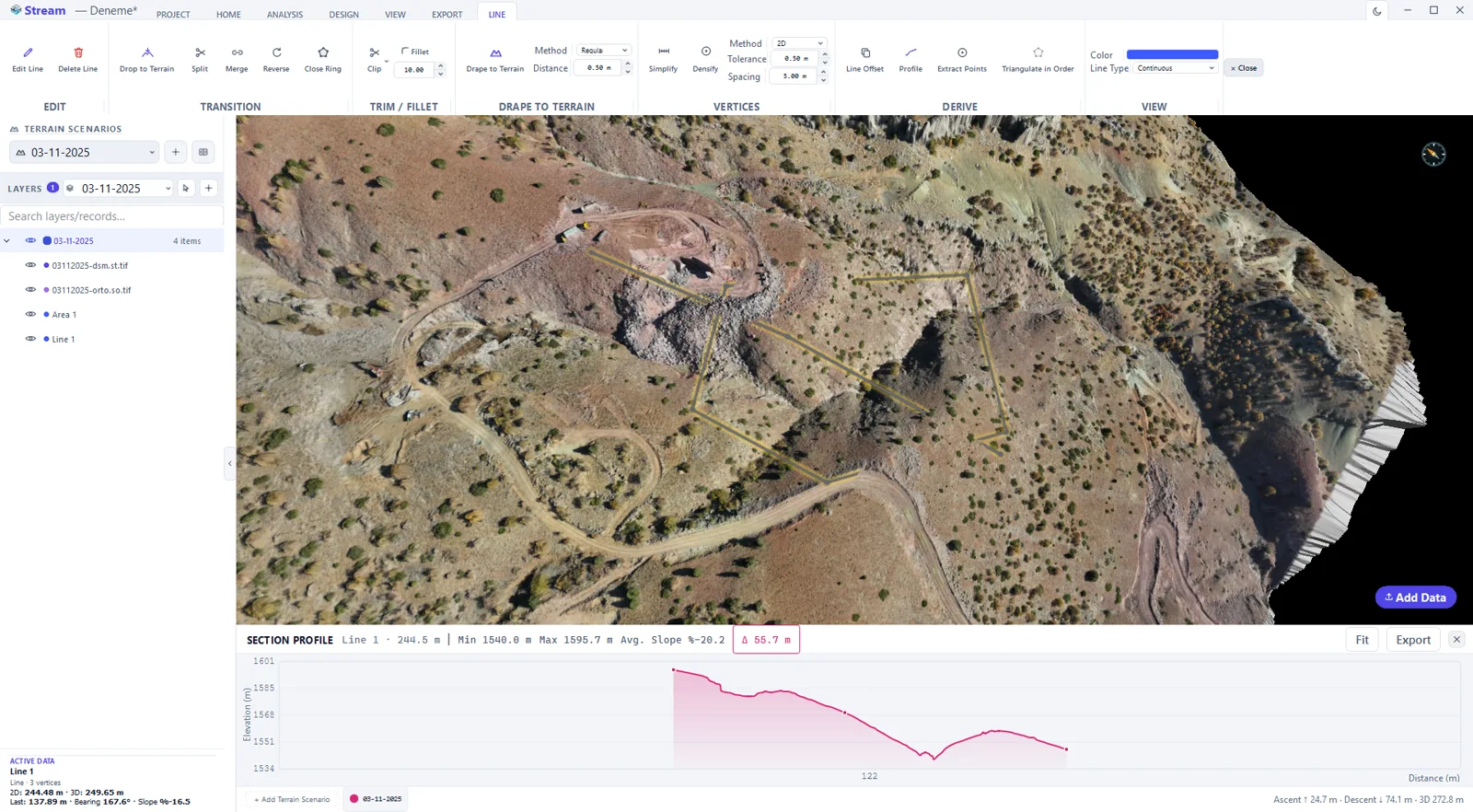
How to compute earthwork cubature from cross-sections
- 1
Set the axis
Draw the centreline with two clicks, or reuse a line you have already drawn on the terrain.
- 2
Set the station interval
Choose the spacing between sections. STREAM cuts a section out of the DEM at every station.
- 3
Pick the surface pair
Choose the upper and lower surfaces the sections are measured between, and set the bulking factor if the quantities are reported loose.
- 4
Read the cubature table
Each station gets its cut and fill area, and the volume between consecutive sections is summed with the average end-area method.
- 5
Export drawings and table
Send the section drawings to DXF for CAD and the station-by-station quantities to Excel or CSV.
Supported formats
Watch it
Frequently asked questions
How does STREAM create cross-sections?
You draw an axis on the terrain with two clicks and set the section interval; STREAM slices a cross-section out of the DEM at every station and measures its cut/fill area.
Can I export the cross-section drawings?
Yes. STREAM exports the cross-section drawings as DXF for CAD, alongside a station-by-station cubature (volume) table.
Which earthworks is this for?
Road, canal, channel and trench earthworks, site grading and quantity takeoff — anywhere station-based cubature is used.
Is STREAM cross section software for earthwork, or a full terrain modeling package?
STREAM is terrain modeling software that includes cross section software as one module — the same DEM and the same terrain model feed the cross-sections, cut/fill areas and cubature table directly, with no separate import step.
What can I compare the ground against?
Four references: a 3D surface, a flat design level you type in, the lowest elevation found inside the area, or a second terrain scenario. Scenario-to-scenario is the default because comparing two surveys is the most common case; the other three cover design work.
How do I set the section axis?
Click two points on the terrain, P1 then P2, or click a line you already drew. The dialog moves out of the way while you pick and a right-click cancels. Afterwards the status line prints the coordinates it captured, so the axis you used is on the record rather than assumed.
My cut and fill came out the wrong way round. Why?
Because the convention is yours to choose. By default, ground above the reference surface is cut and ground below it is fill. If your organisation uses the opposite sign, tick the invert option and recalculate — STREAM does not guess which convention you meant.
What section interval should I use?
Anything from 0.1 upward, in your active unit. The interval controls the drawings and the table; it does not control the accuracy of the volume, which is computed on the terrain surface itself. Tighten it where the ground changes quickly and you need the drawing to show it.
What is the mass-haul column for?
It is the running net of cut minus fill along the chainage. Where the curve rises you have surplus material, where it falls you need to import, and where it crosses zero the earthwork balances — which is how you decide where to move material rather than truck it off site.
Can I apply a swell factor?
Yes, as a multiplier on the fill volume, from 0.5 to 3. Set it to 1 to keep in-situ volumes. The starting chainage of the ruler and a vertical exaggeration for the DXF drawing are set in the same place.
What comes out of a cross-section run?
A volume schedule as Excel or CSV — chainage, cut area, fill area, volume and cumulative mass haul, in the unit system on screen — and the section drawings as DXF with the vertical exaggeration you chose. Both are exported from the preview after the calculation has run.
Try Cross Section in STREAM
Free beta for Windows x64. Works fully offline with GeoTIFF, LAS/LAZ and DXF.
Download STREAM free