ROAD DESIGN SOFTWARE
Road Design Software That Works on Your Own Terrain
STREAM is road and corridor design software that runs directly on the terrain model you already have. Draw the horizontal alignment on the DEM, shape the vertical profile, define the typical section, and STREAM builds the road surface, checks it against the standards you set, and returns the earthwork quantities and drawings.
What is corridor design?
Corridor design turns a line on the ground into a buildable road surface. The horizontal alignment sets where the road goes, the vertical profile sets how it rises and falls, and the typical section sets how wide it is and how its side slopes meet the ground.
Once those three are defined, everything else follows: the cut and fill at each station, the balance between them, and the drawings the construction crew works from.
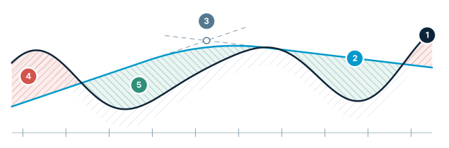
Road profile — grade, vertical curve, quantities
The ground line comes from the DEM, the grade line from tangents and a vertical curve. Cut and fill are the difference.
- Ground line — existing terrain read from the DEM
- Grade line — the design profile
- Vertical curve — the parabola easing two grades together (PVI)
- Cut — ground sits above the grade line
- Fill — ground sits below the grade line
Road Design Software in STREAM
Horizontal alignment
Place PI vertices on the terrain and set circular curves by radius, with clothoid transitions where you need them.
Vertical profile
Set PVI points, grades and vertical curves; the ground line comes straight from your DEM so the design always sits on real terrain.
Typical section and superelevation
Define carriageway width, shoulders and cut/fill batter slopes, then apply cross slope through curves by edge or axis rotation.
Cross-sections and quantities
Get the section at every station with its cut and fill areas, a station-by-station quantity table, and a mass haul view of the cut/fill balance.
Standards checking
Enter your limits for maximum grade, minimum radius and sight distance; every edit is re-checked and violations are listed with the station and the limit they break.
Full-resolution surface
Cross-sections are taken at the interval you choose, but the road surface is built at the full resolution of the terrain — volumes follow the real surface, not the section spacing.
Horizontal alignment with clothoids
Draw the alignment or take an existing polyline from the project as the centreline. Each interior PI carries a curve radius and a clothoid parameter; a radius that will not fit between the tangents is reduced to the largest one that does and the plan says so, rather than drawing a curve that cannot be built.
Vertical profile with K values
Add PVIs on the long-section graph and give each one an elevation or a grade — the elevation then follows from the previous PVI. Interior PVIs take a parabolic vertical curve length, and the K value, the steepest grade and any grade limit you set are shown live, with the violating stations named.
Superelevation and cross-section templates
One typical section applies along the whole corridor and can be overridden station by station. Superelevation is defined per curve with the full rate, and where a clothoid exists the transition is run over its length instead of an arbitrary runoff.
Mass haul and a control tab
Cut and fill totals update live per station, with a warning when a section's batter did not daylight or when the DEM did not cover a station. A dedicated control tab lists every alignment, profile and section violation instead of leaving you to notice a bad number.
Setting-out lines and terrain application
Draw Plan writes the lane edges, shoulder edges, lane line, bench inner and outer edges, ditch centrelines and the daylight line into the project as named line records. Apply to Terrain rasterises the design surface — platform, batters, benches and ditches — into the DEM as a layer you can switch off, and turns amber when the design has moved on.
How to design a road corridor in STREAM
- 1
Open the module
Start a corridor session from the design tab. Its own ribbon appears and stays until you close the session.
- 2
Draw the horizontal alignment
Place the intersection points on the terrain and set each curve by radius, adding clothoid transitions where they are needed.
- 3
Shape the vertical profile
Set the grade change points, the grades between them and the vertical curves. The ground line under the profile is read from your DEM.
- 4
Define the typical section
Enter carriageway width, shoulders and the cut/fill batter slopes, then set how superelevation is applied through the curves.
- 5
Apply and check
Write the road surface into the terrain and review the standards check — every violation is listed with the station and the limit it breaks.
- 6
Export
Send plan, profile and cross-section drawings to DXF, and the quantity table and design report to Excel and PDF.
Supported formats
Watch it
Frequently asked questions
What can STREAM's road design module do?
It covers horizontal alignment with circular curves and clothoid transitions, the vertical profile with grades and vertical curves, the typical section, superelevation, cross-sections with cut/fill areas, and a mass haul view of the earthwork balance.
Does the road design work on my own terrain data?
Yes. The alignment is drawn on your DEM and the ground line at every station is read from it, so the design sits on the real surface rather than an idealised one.
Can STREAM check the design against standards?
You enter the limits that apply to your project — maximum grade, minimum radius and sight distance — and STREAM re-checks the design on every edit, listing each violation with the station where it occurs and the limit it breaks.
What drawings and reports can I export?
Plan, longitudinal profile and cross-section drawings export to DXF for CAD, and the design report with the quantity table exports to PDF.
Does the cross-section interval affect the calculated volume?
No. Cross-sections are taken at the interval you choose for the drawings, but the road surface itself is built at the full resolution of the terrain, so the volume follows the real surface.
What station interval can I use?
5, 10, 20, 25 or 50 in your active length unit, or any custom value from 1 to 500. There is also an option to halve the interval through curves, so the sections get denser exactly where the geometry changes fastest.
Does STREAM support transition curves?
Yes. Each interior PI takes a radius and a clothoid parameter. Where a clothoid is present the superelevation transition is run over its length rather than an invented runoff, which is the behaviour a road standard expects.
What happens if a curve radius does not fit?
It is reduced to the largest radius that fits between the tangents, and the plan view labels that curve as not having fitted, with the advice to reduce the radius. Nothing is silently drawn that could not be built.
How is the vertical profile defined?
By PVIs on the long section. Give a PVI an elevation, or give it a grade and let the elevation follow from the previous PVI as z = z_prev + g·Δs/100. Interior PVIs take a parabolic vertical curve length, and STREAM reports the K value beside it. The first and last PVI cannot be deleted and cannot carry a vertical curve.
Can I check the design against a maximum grade?
Yes. Enter a grade limit and the steepest grade badge shows the achieved value against it, turning red on exceedance and naming the offending stations in the tooltip. The control tab collects those findings together with the alignment and section violations.
Can I manage more than one road in a project?
Yes. Alignments are named and kept in a list; adding a new one saves the current design under its name and clears the panel. Renaming and deleting are available, and deleting a design explicitly leaves the centreline layer and any applied road surface in the project rather than removing them behind your back.
What does STREAM write out for a corridor?
DXF with the centreline, batter lines and sections; an Excel sheet of the station-by-station cut and fill; and a signable PDF report with the summary, the section schedule and the plan sheets. The setting-out lines can also be written into the project as line records, and the design surface can be applied to the terrain as a removable layer.
Try Road Design in STREAM
Free beta for Windows x64. Works fully offline with GeoTIFF, LAS/LAZ and DXF.
Download STREAM free