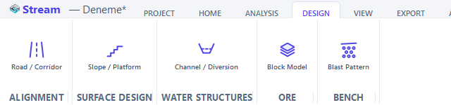
The Design tab
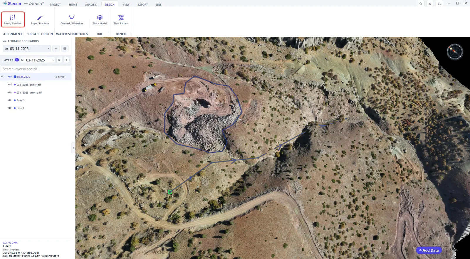
The DESIGN tab lists the modules: Road / Corridor and Slope / Platform (the surface design), Channel / Diversion (water structures), Block Model (ore) and Blast Pattern (bench). Click one to open its editor.
The design modules on the Design tab.
Road and corridor design step by step
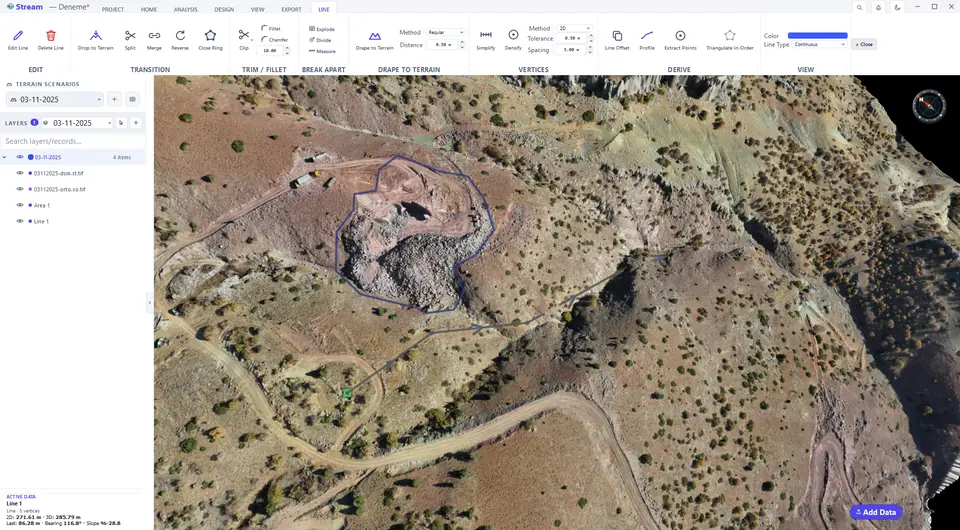
Open it from DESIGN ▸ ALIGNMENT ▸ Road / Corridor. Draw the road centre line on the terrain first, or turn an existing line into the axis with Pick Polyline.
Draw the road center line.
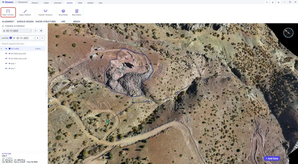
Open Road / Corridor on the Design tab.
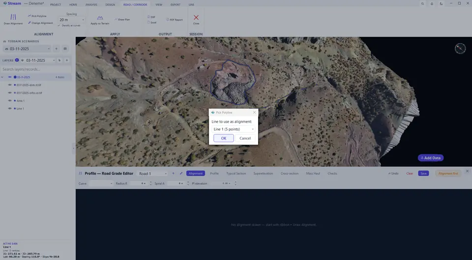
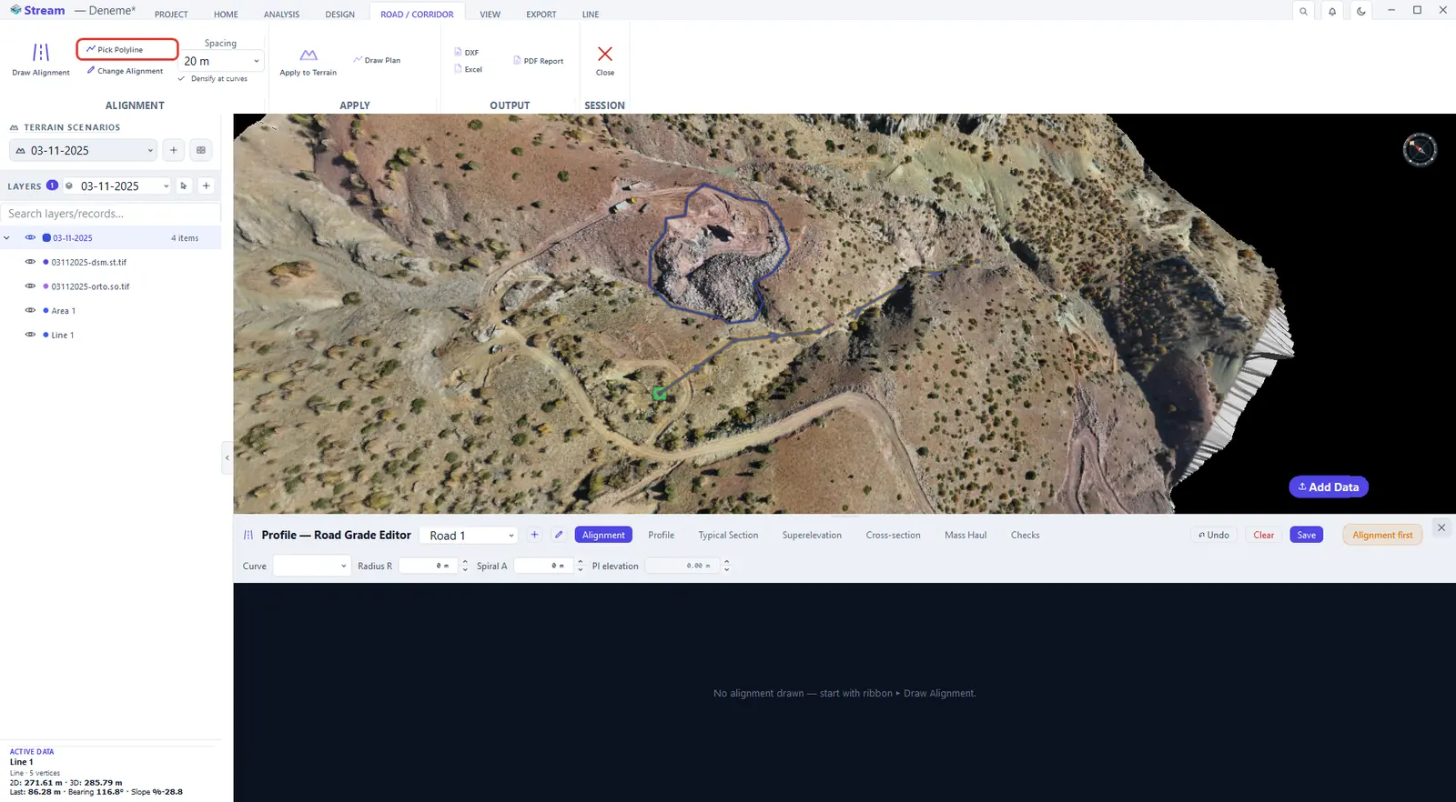
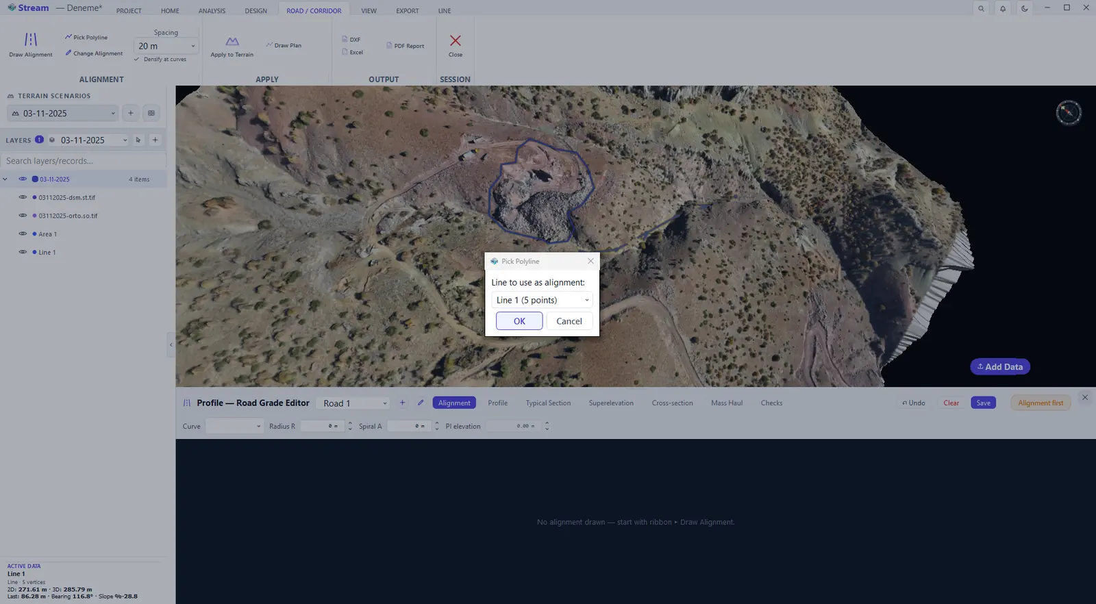
Press Pick Polyline.
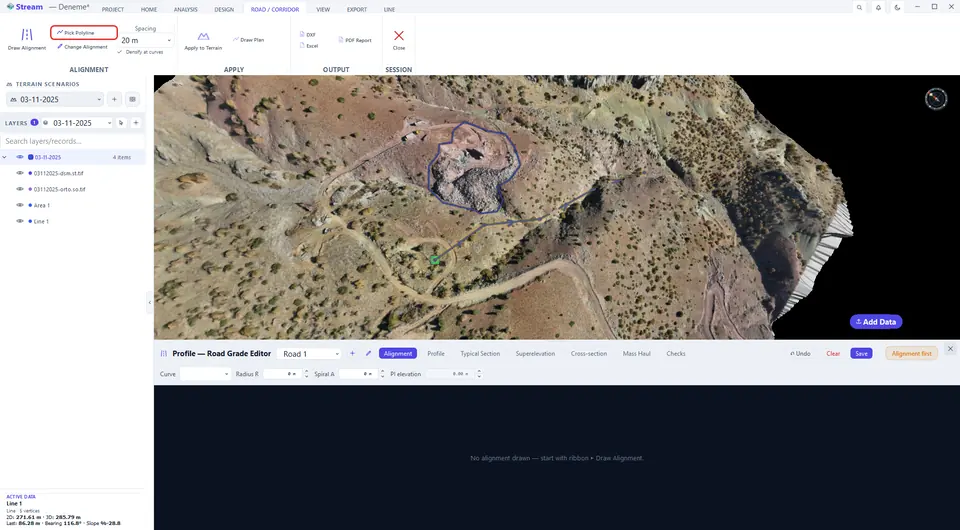
Press Pick Polyline - pick from the list.
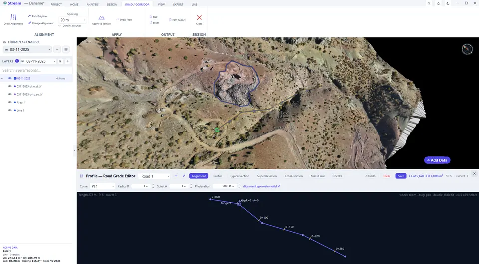
The ground profile is sampled along the alignment.
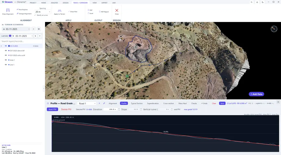
Profile tab.
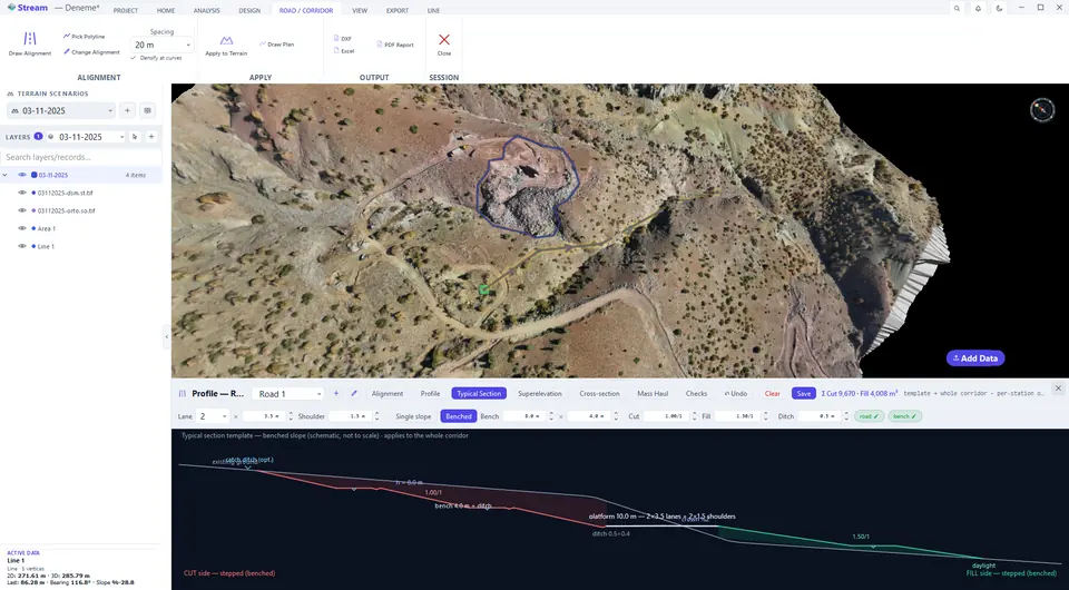
Typical Section tab.
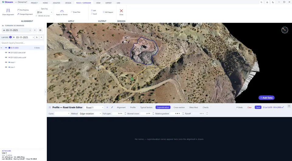
Superelevation tab.
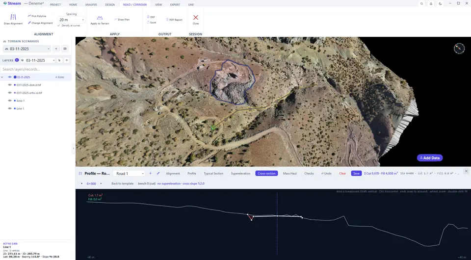
Cross-section tab.
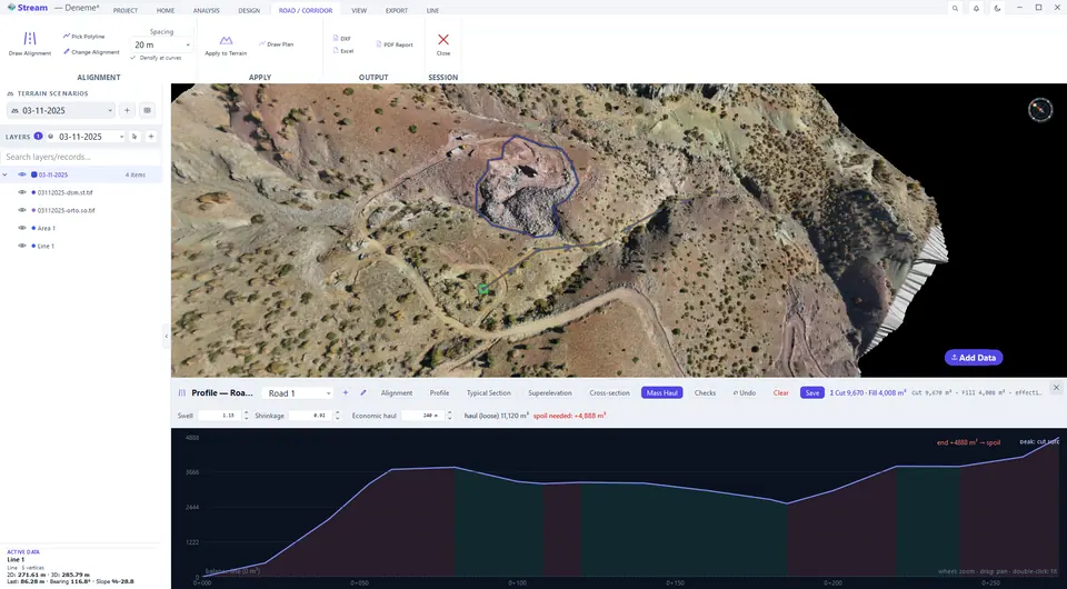
Mass Haul tab.
Checks tab.
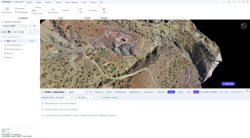
Press Apply to Terrain.
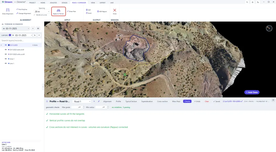
The design is cut into the terrain.
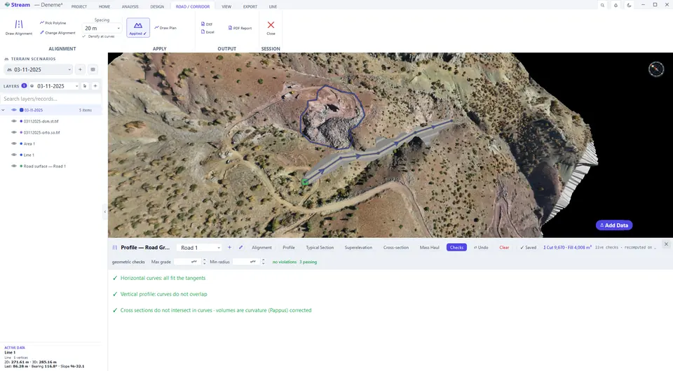
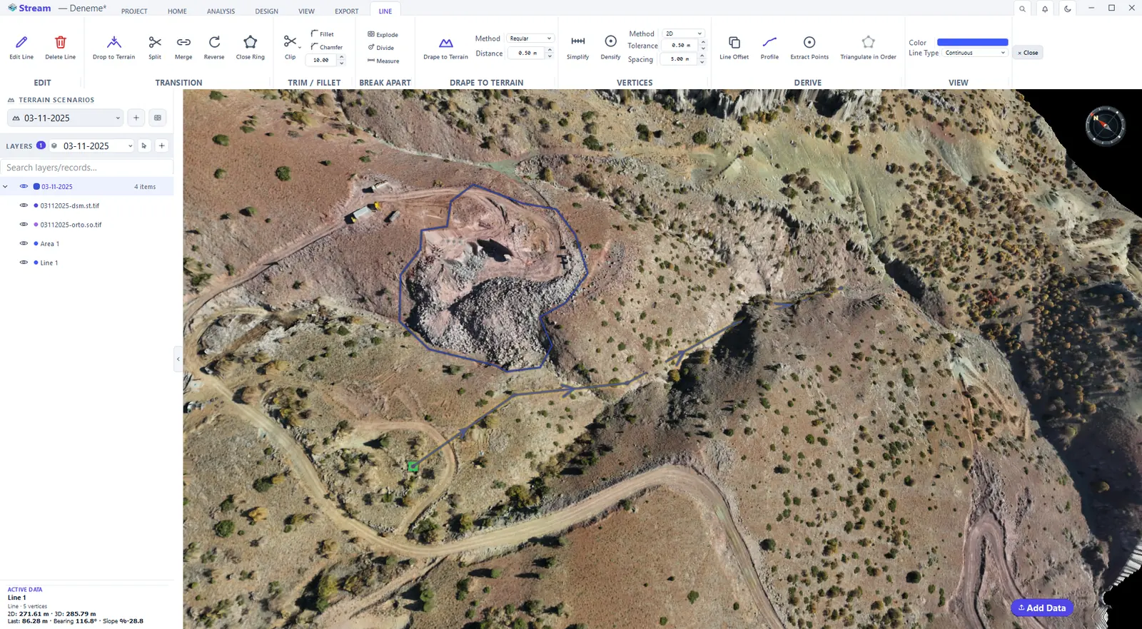
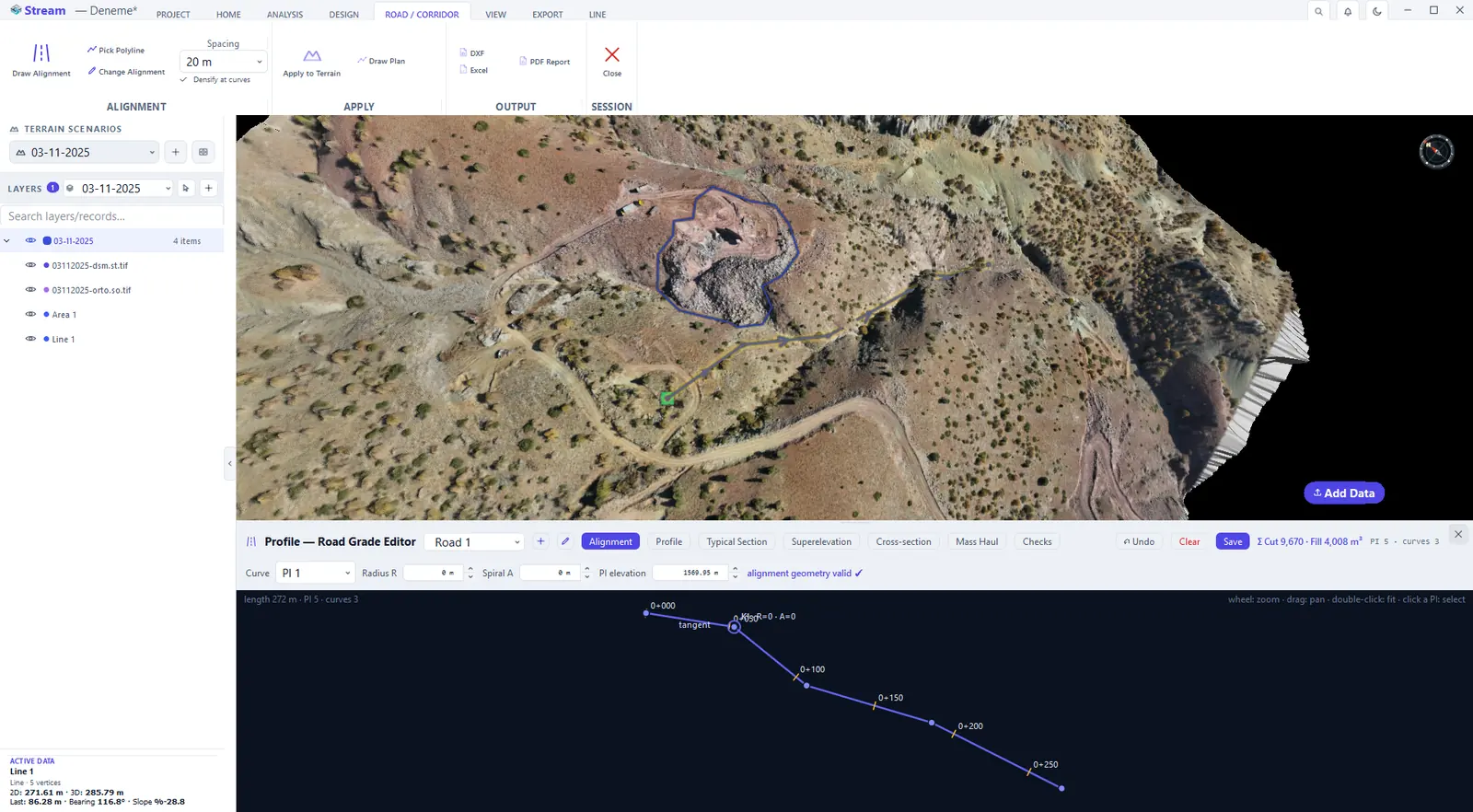
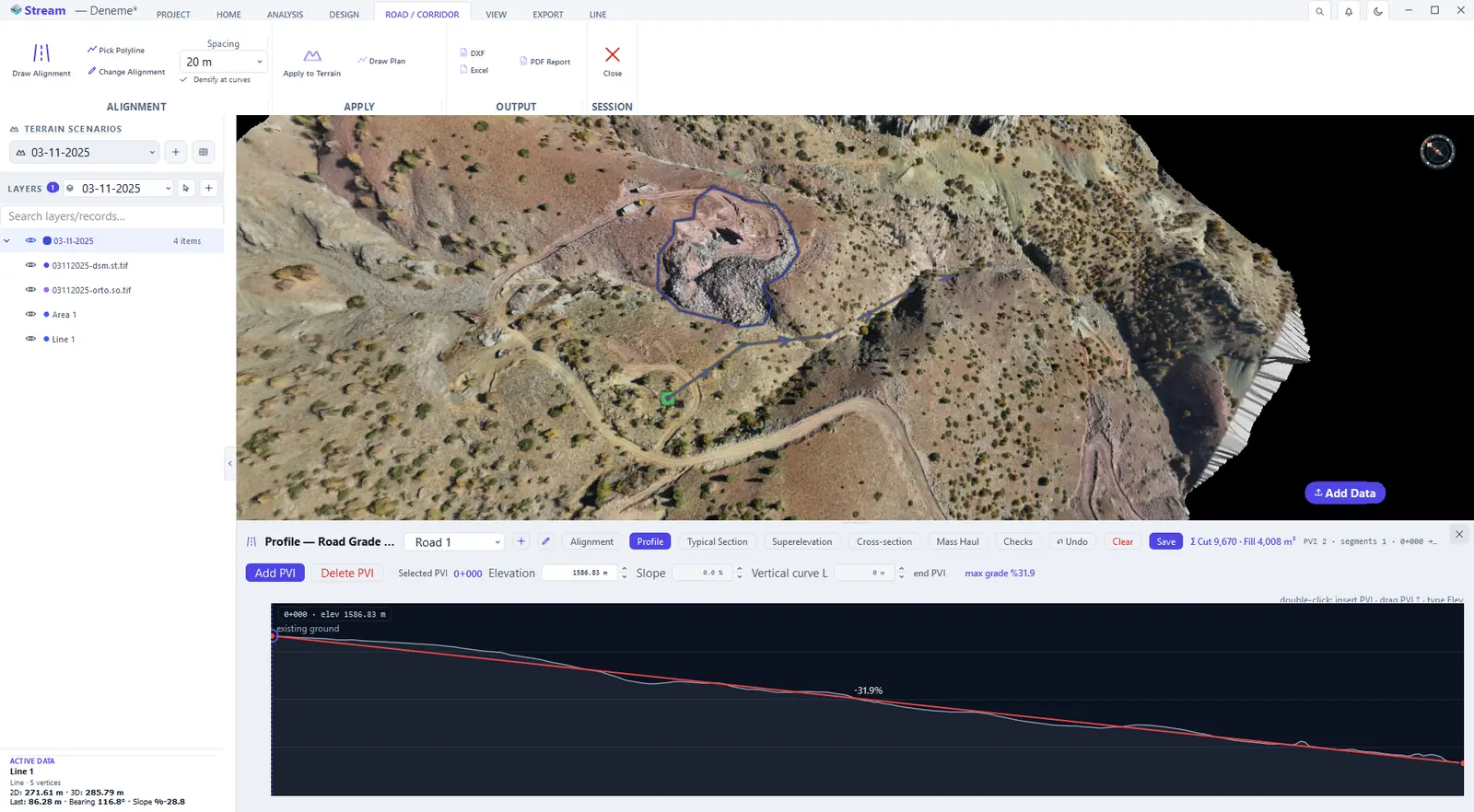
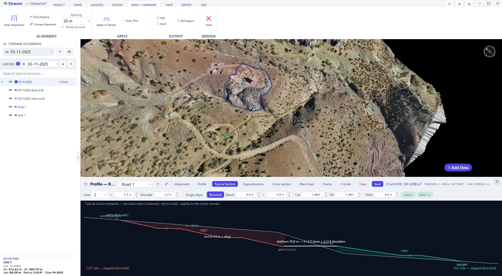
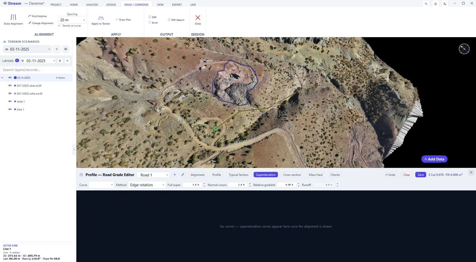
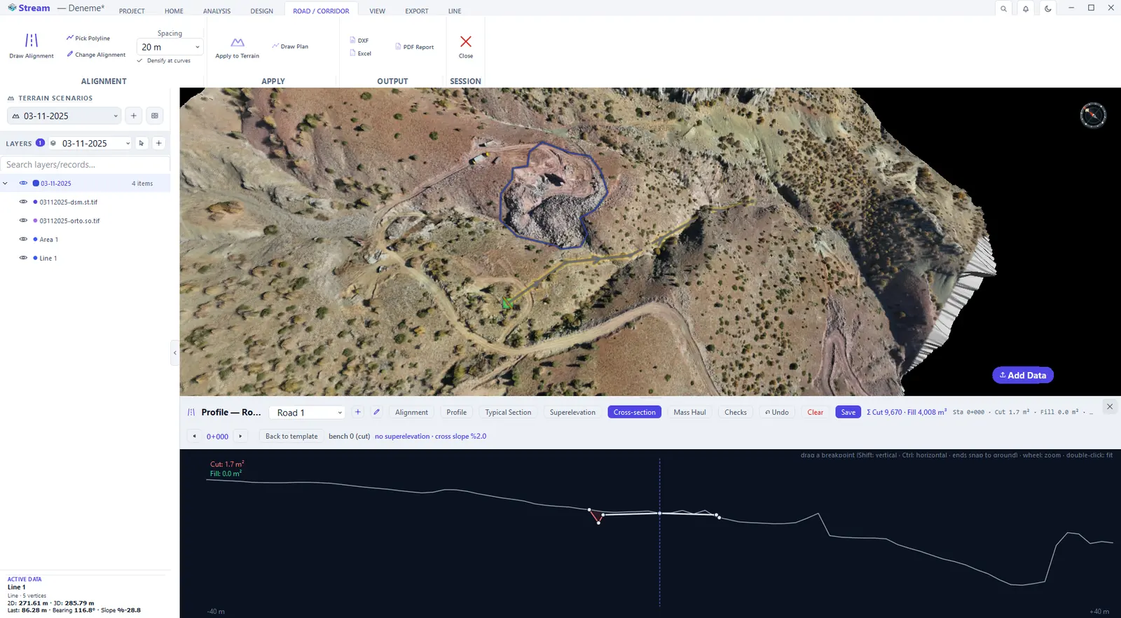
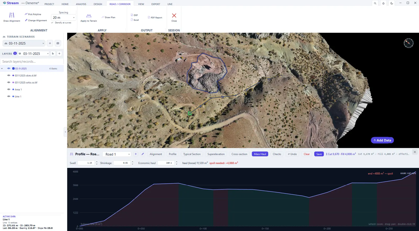
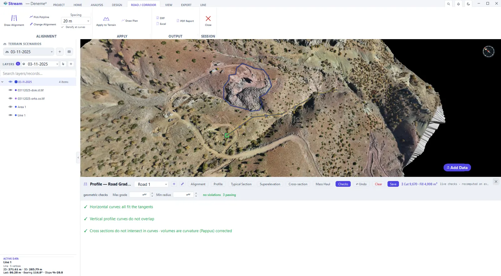
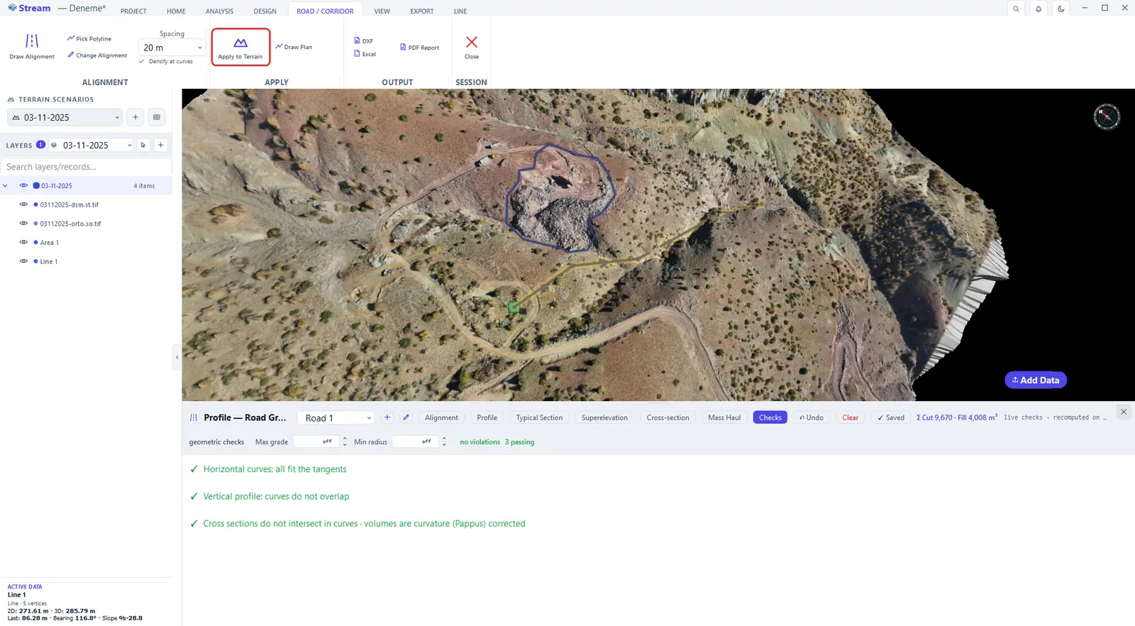
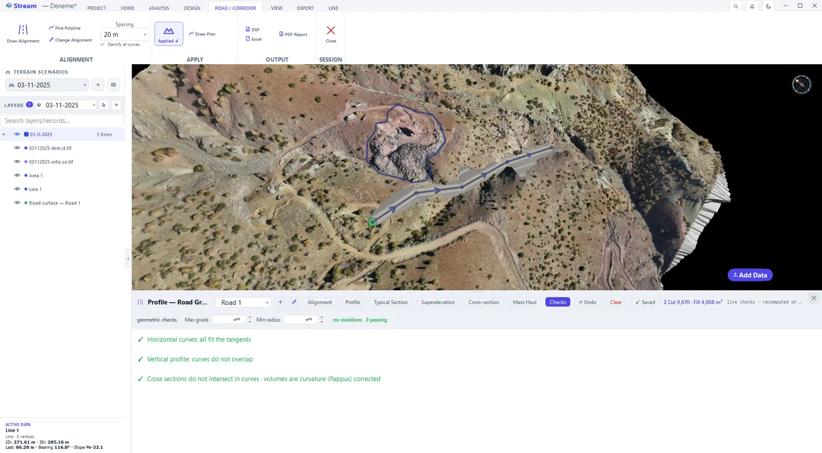
The editor has seven tabs; working through them in order is easiest:
- Alignment — the horizontal axis: PI vertices, curve radius (R) and spiral transitions (A). The PI elevation sets the design elevation of the selected vertex.
- Profile — the vertical axis: PVI points, grades and vertical curves (K value), drawn against the sampled ground profile.
- Typical Section — carriageway width, shoulders and cut/fill batter slopes.
- Superelevation — cross slope through the curves; edge-rotation or axis-rotation method. The tab stays empty on a straight alignment.
- Cross-section — the section at each station with its cut and fill areas (m²).
- Mass Haul — the cut/fill balance and the haul distance along the road.
- Checks — maximum grade, minimum radius and sight distance are checked on every change; violations are listed with their station and limit.
Apply to Terrain cuts the design into the ground. Plan, profile and cross-sections export to DXF, the quantity table to a spreadsheet and the design report to PDF.
Related features
What each capability does, which formats it reads and writes, and answers to common questions: