Add a point on the terrain
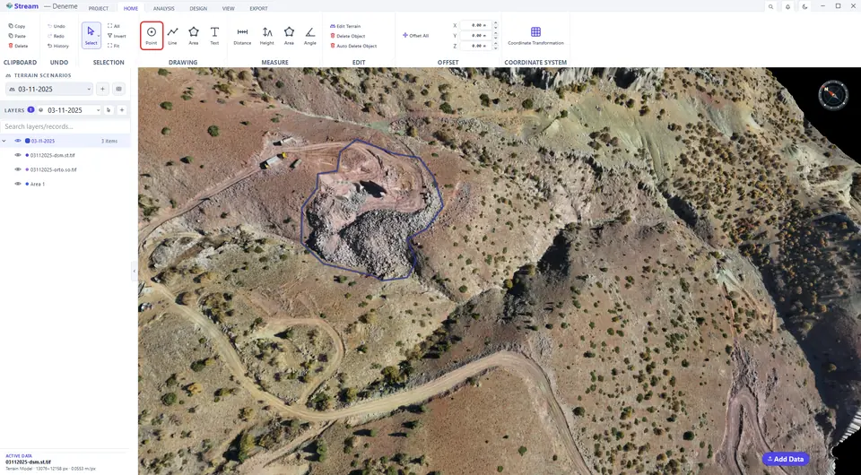
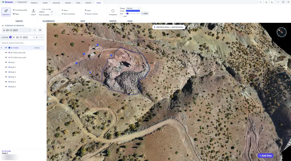
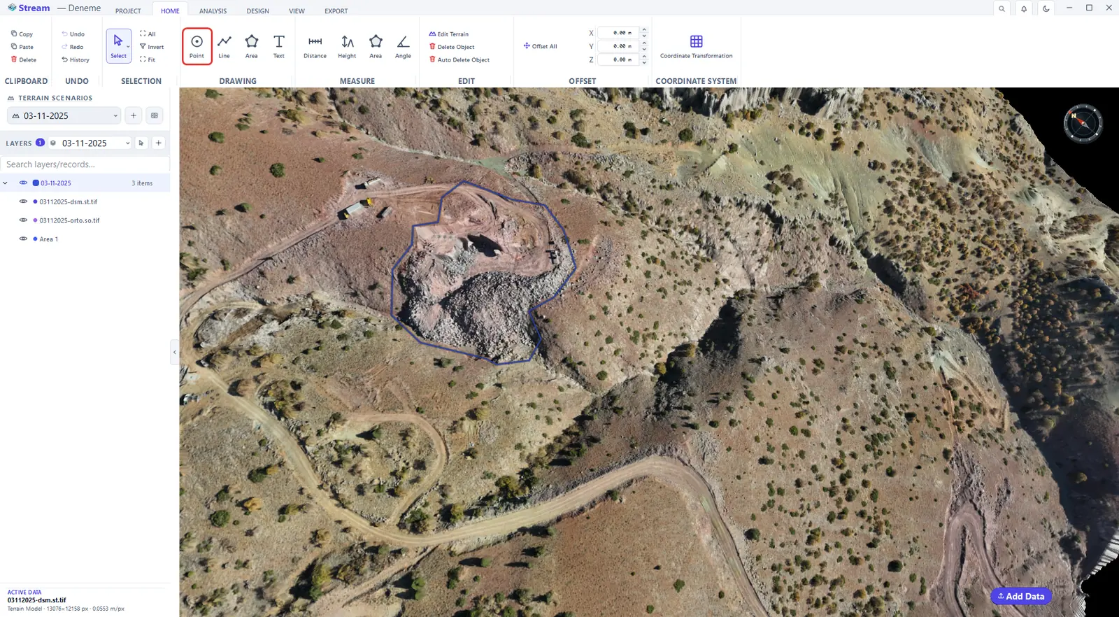
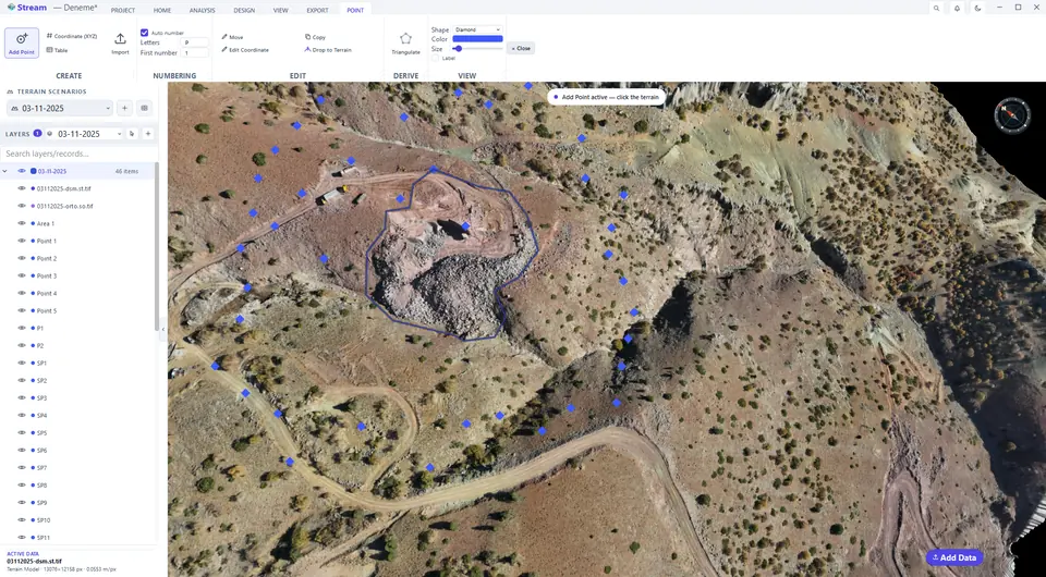
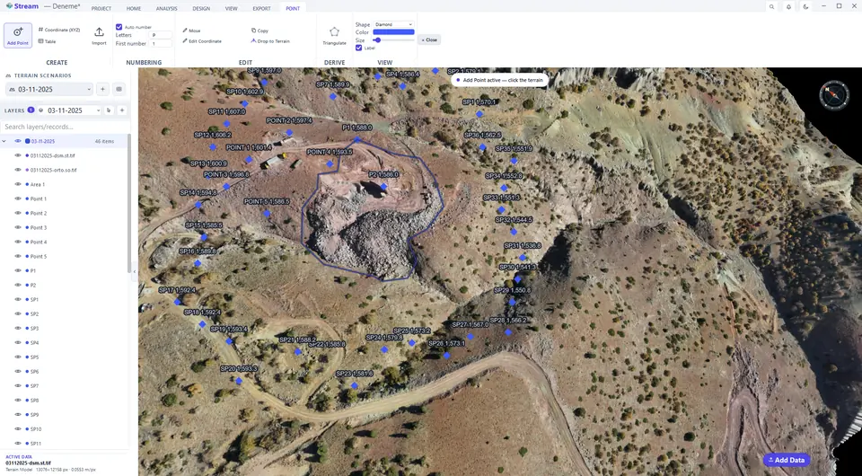
Click HOME ▸ DRAWING ▸ Point. The POINT tab opens and the view shows Add Point active — click the terrain. Each click places a point on the surface; X, Y and Z are read automatically. Every point becomes a row in LAYERS.
Pick the Point tool on the Home tab.
Click on the terrain to place points.
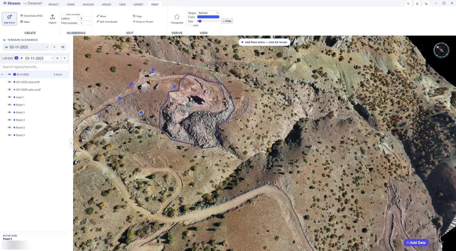
With a point selected, the POINT tab also holds Move, Edit Coordinate (change the position numerically), Copy and Drop to Terrain.
Number points automatically
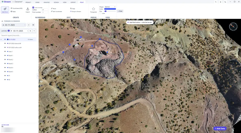
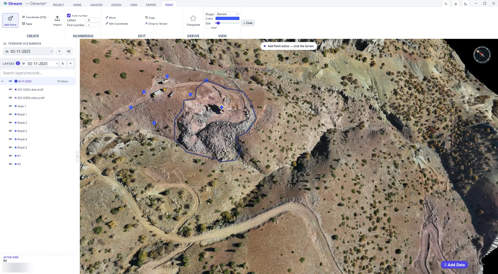
The NUMBERING group names new points in sequence. Tick Auto number, type the Letters (the prefix) and the First number: the next points become P1, P2, P3 … or P101, P102 … if you start at 101.
Turn on Auto number and set the prefix.

New points take the next number.
Add a point by coordinates
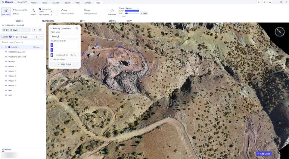
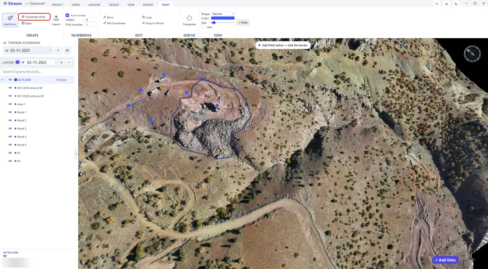
To create a point at an exact location instead of clicking, use Coordinate (XYZ) on the POINT tab. Type the easting (X) and the northing (Y); leave Z on automatic (terrain) to read the elevation from the surface, or type a value.
Open Coordinate XYZ entry on the Point tab.
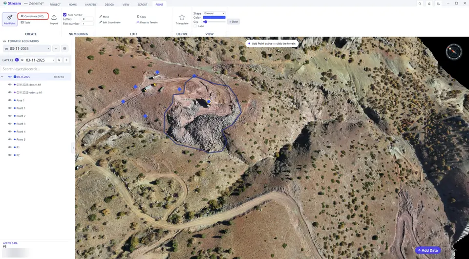
Type the easting (X) and northing (Y); leave Z on automatic to read the elevation from the terrain.

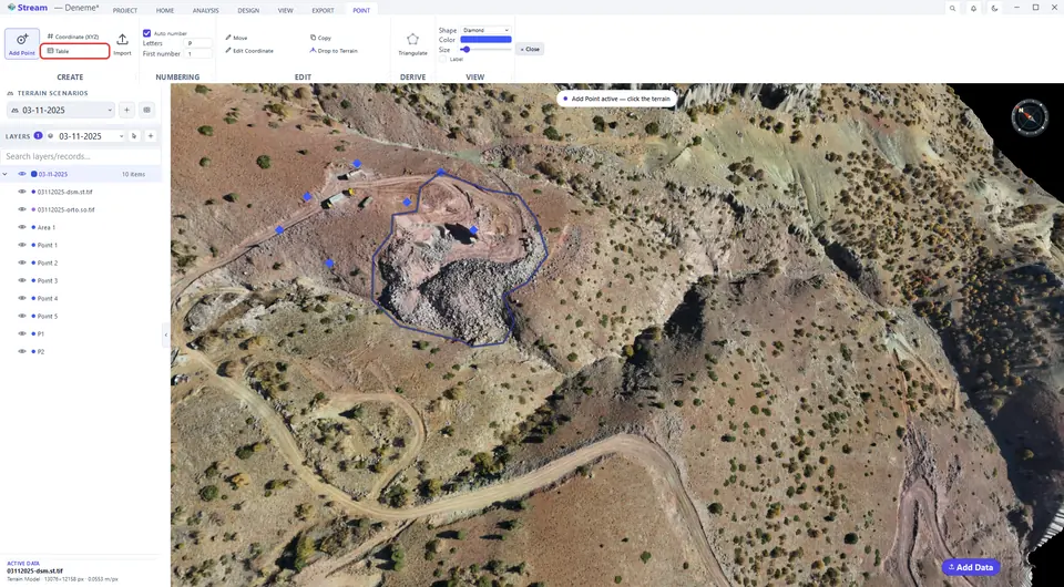
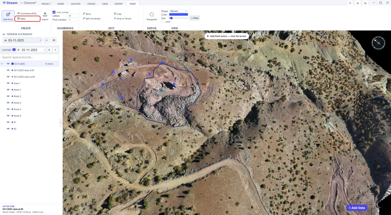
Open the point table
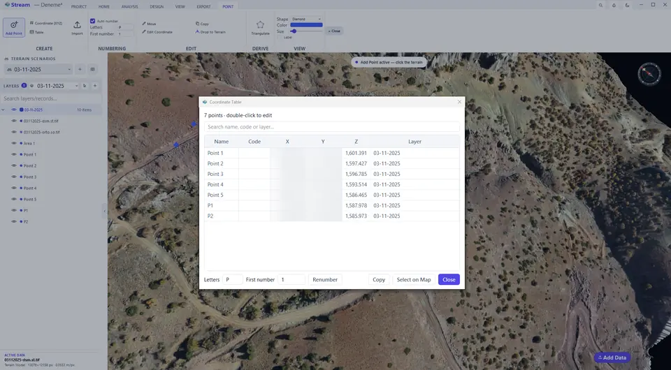
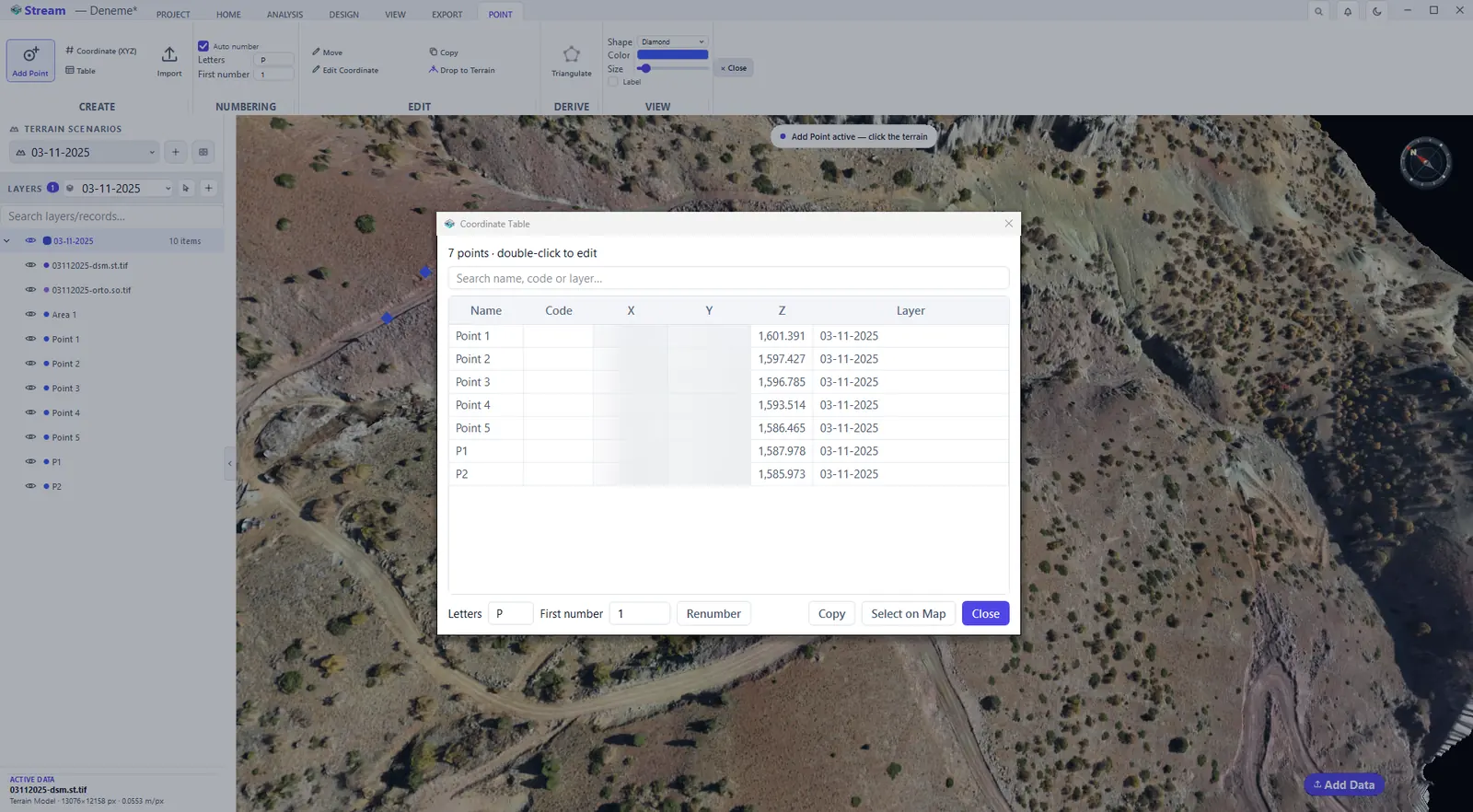
Table lists every point with its code, coordinates and layer. Double-click a cell to edit a name, a code or a coordinate in place, sort by any column, or renumber the selected rows with letters and a first number. The search box filters by name, code or layer; Copy puts the selected rows on the clipboard, ready to paste into Excel; Select on Map selects the rows' points in the view.
Open the point table.
Every point with its coordinates.
Import survey points from a CSV file
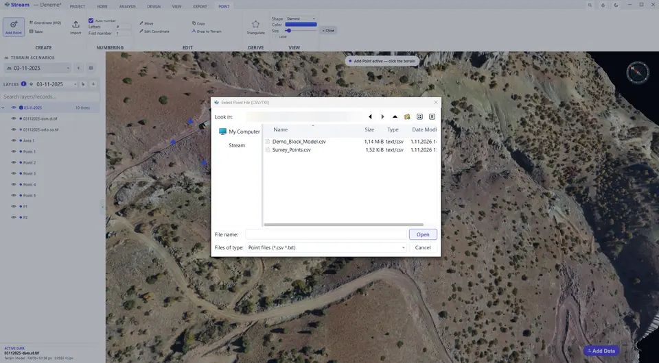
Import on the POINT tab reads a point list from a CSV or TXT file.
Choose a CSV survey file.
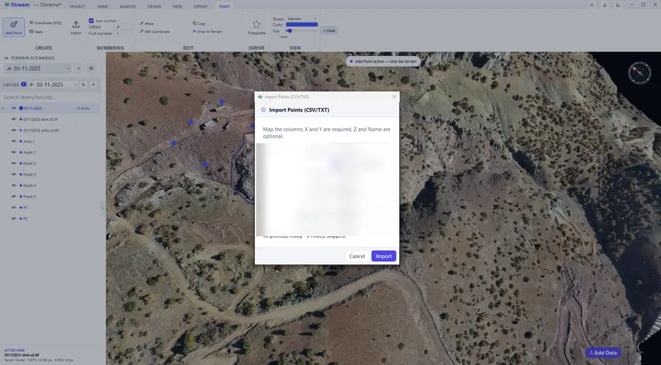
Match the columns and import.
Survey points on the terrain.
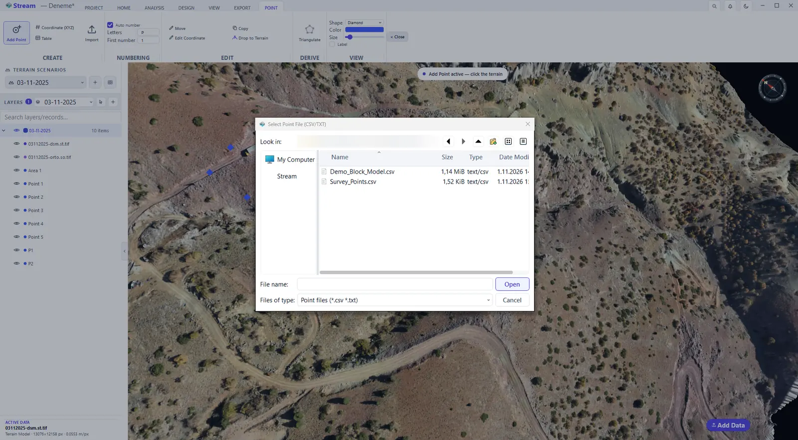
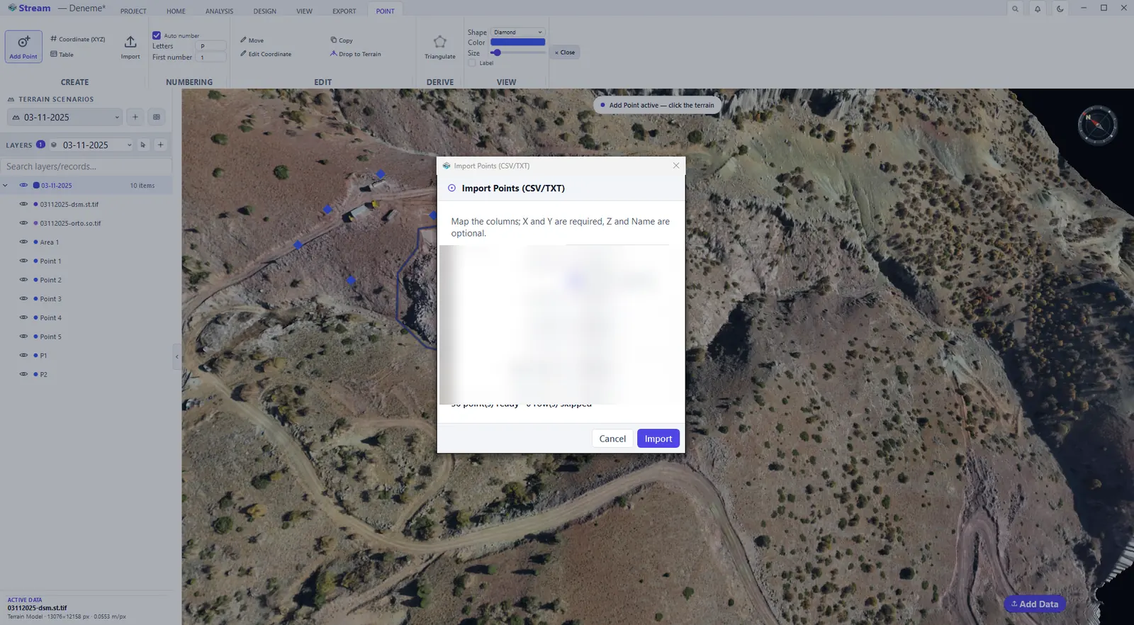
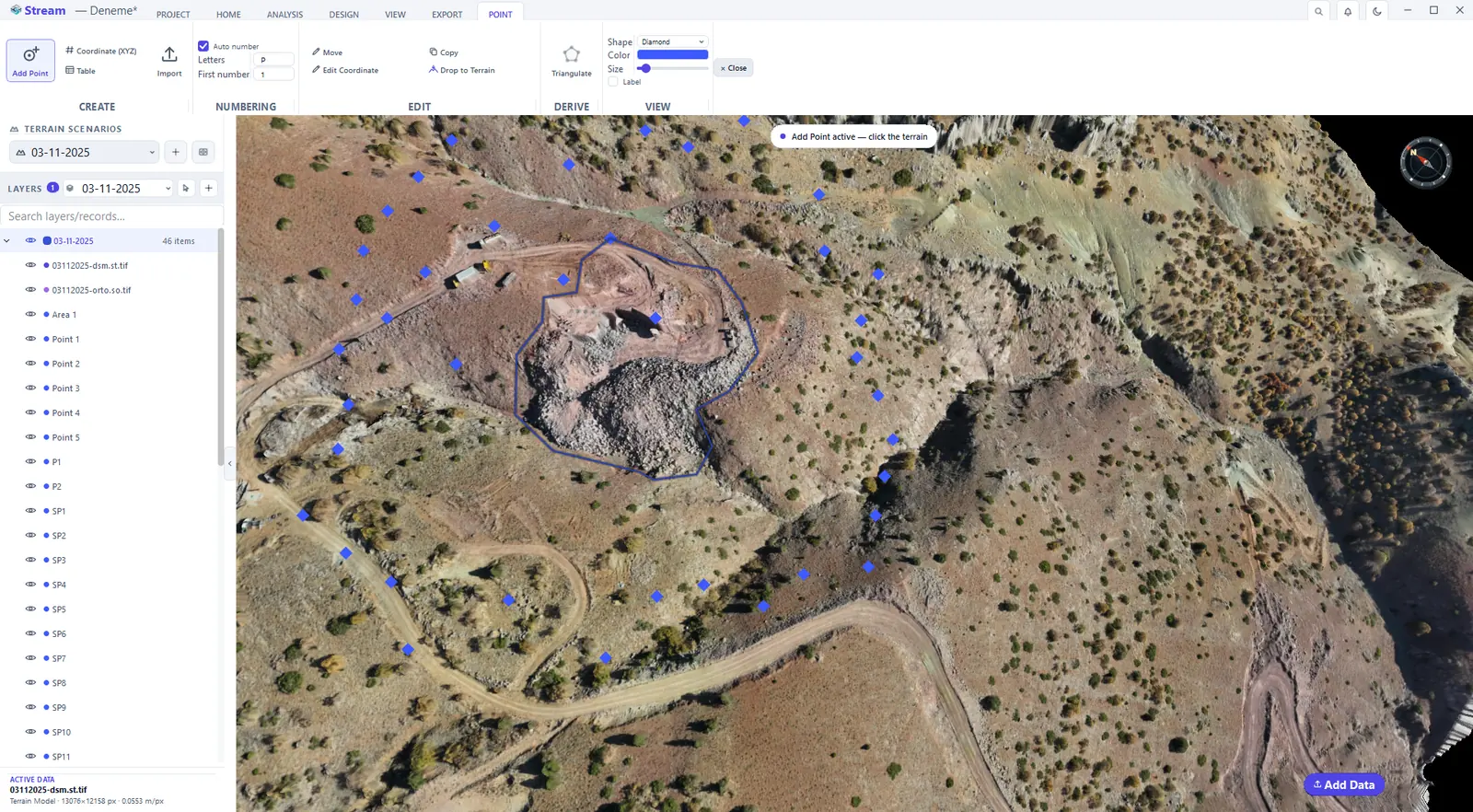
Map the columns of the file: X and Y are required, Z and Name are optional. The dialog reports how many points are ready and how many rows are skipped. When the import finishes, the points are drawn on the terrain and listed in LAYERS.
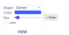
Change point shape, color, size and labels
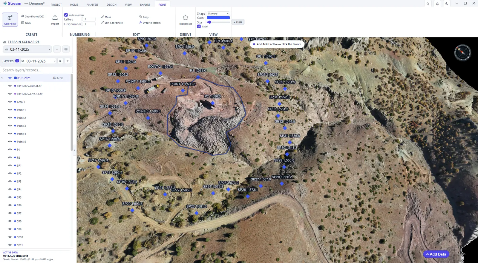
Shape and Color apply to the selected points and to new points; Size and Label are project settings that apply to all points. Switch Label on to write each point's name and elevation next to it.
Shape, color, size and labels on the Point tab.
Point labels shown on the map.
Build a TIN surface from points
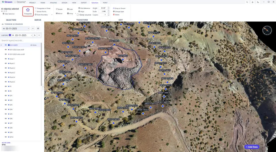
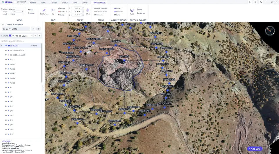
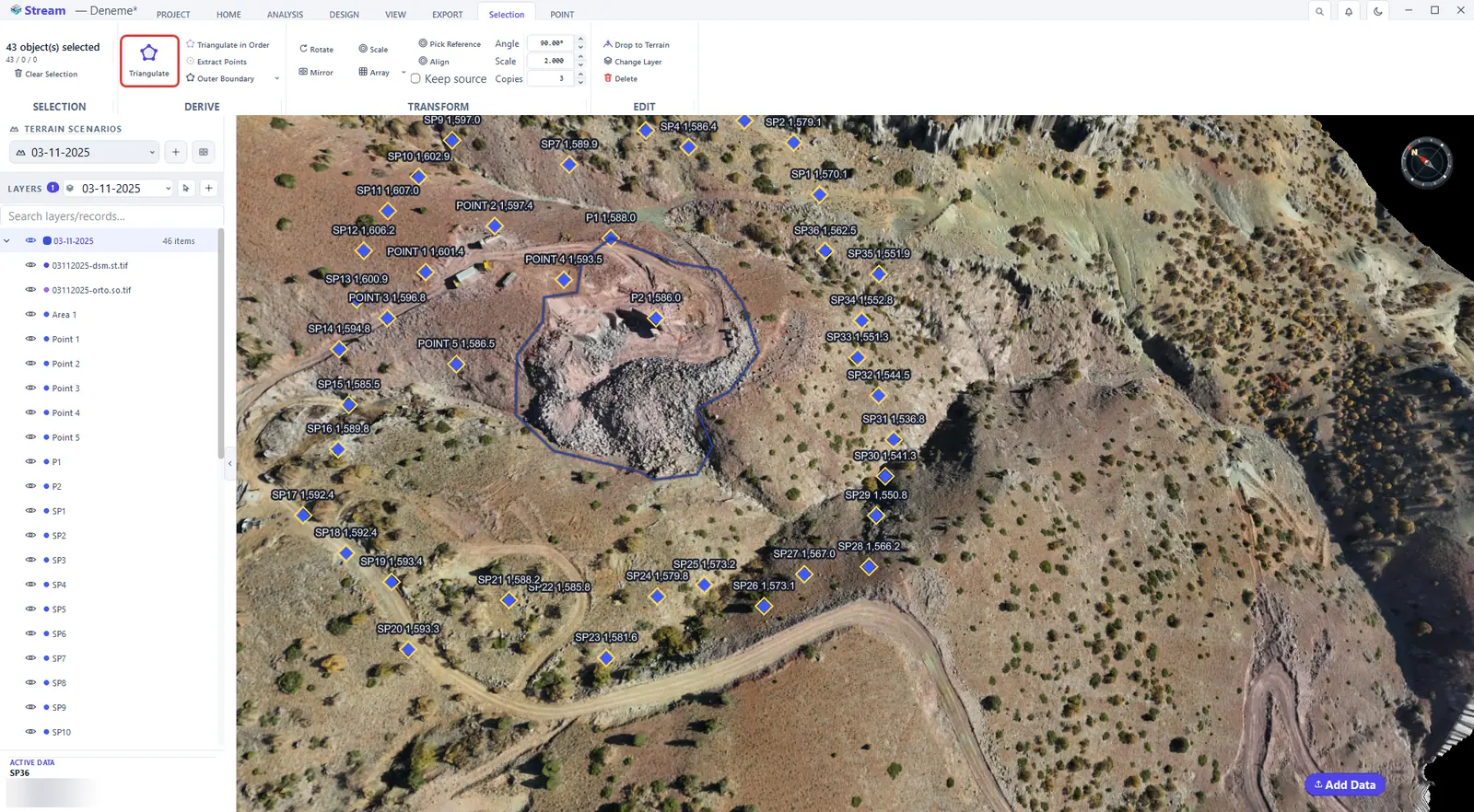
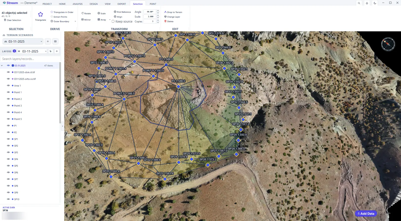
A TIN (triangulated irregular network) is a surface made of triangles whose corners are your points. Select the points — Ctrl-click, or HOME ▸ SELECTION ▸ All — and press Triangulate. The new surface is a triangle model record; the TRIANGLE MODEL tab opens.
Select the points and press Triangulate.
TIN surface built from the points.
Color the model by elevation or slope.
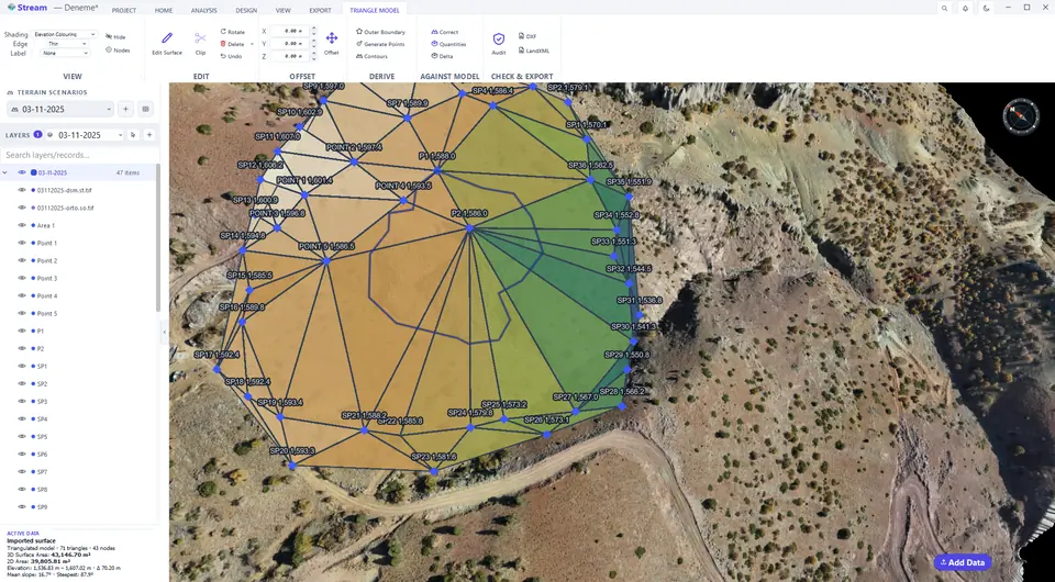
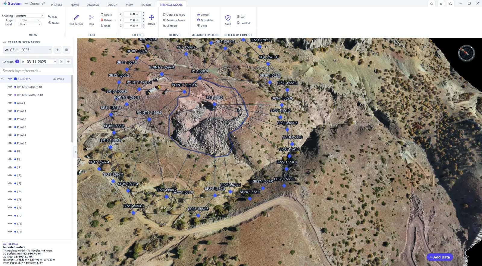
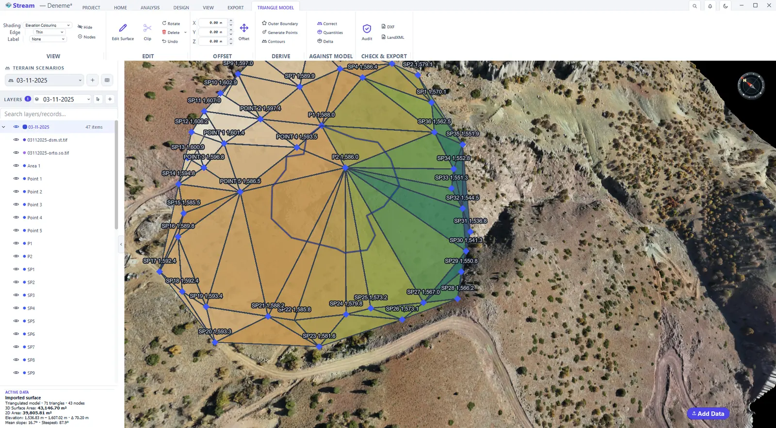
The model can be shaded by elevation, by slope, with a flat colour or as a wireframe — a display choice that does not change the model.
Triangle model tools: contours and model check
The TRIANGLE MODEL tab groups what you can do with a surface: edit it, offset it, derive new objects from it, compare it with the terrain and check and export it.
Triangle Model tab: edit, derive, compare, export.

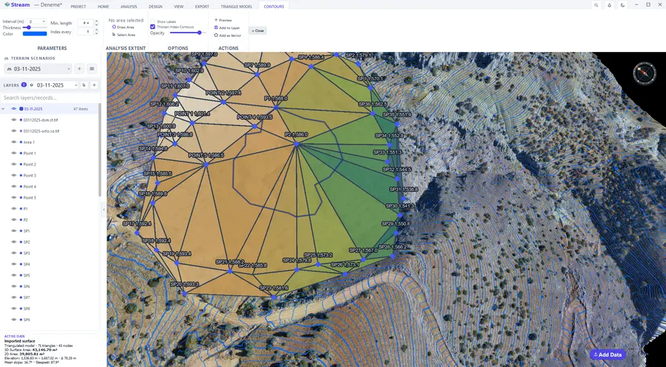
Contours builds contour lines from the model.
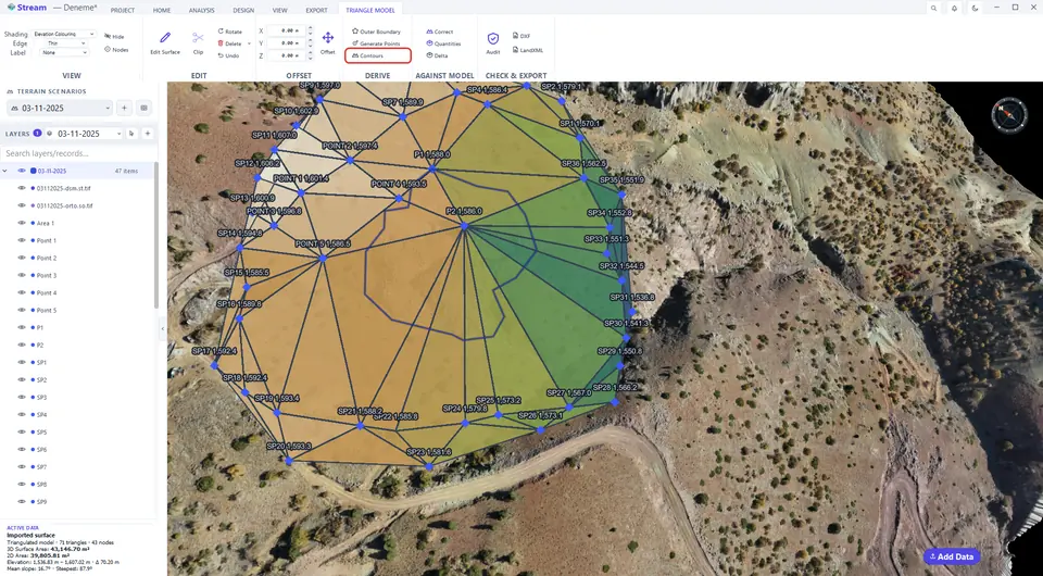
Contours from the model.
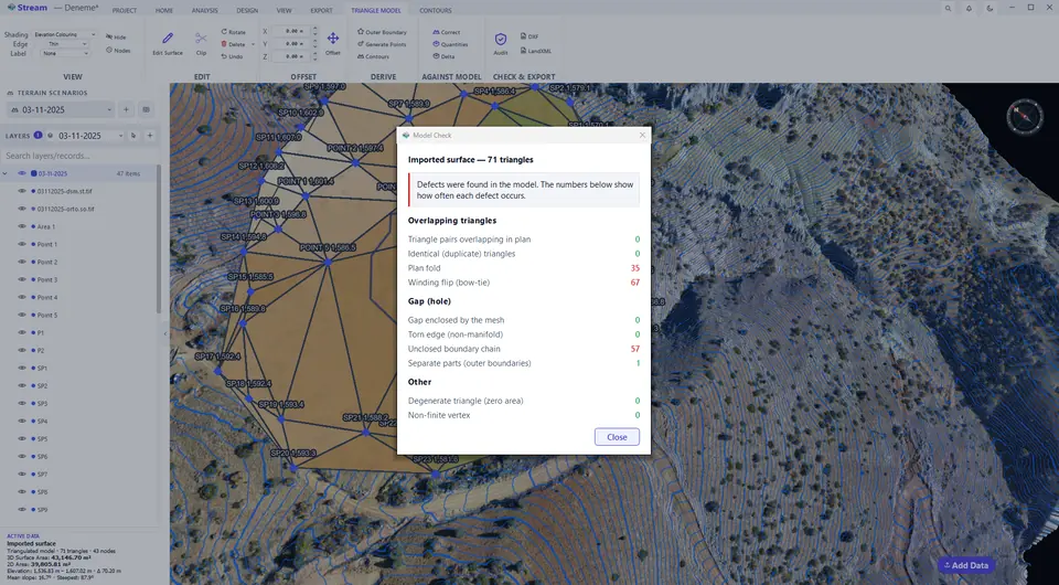
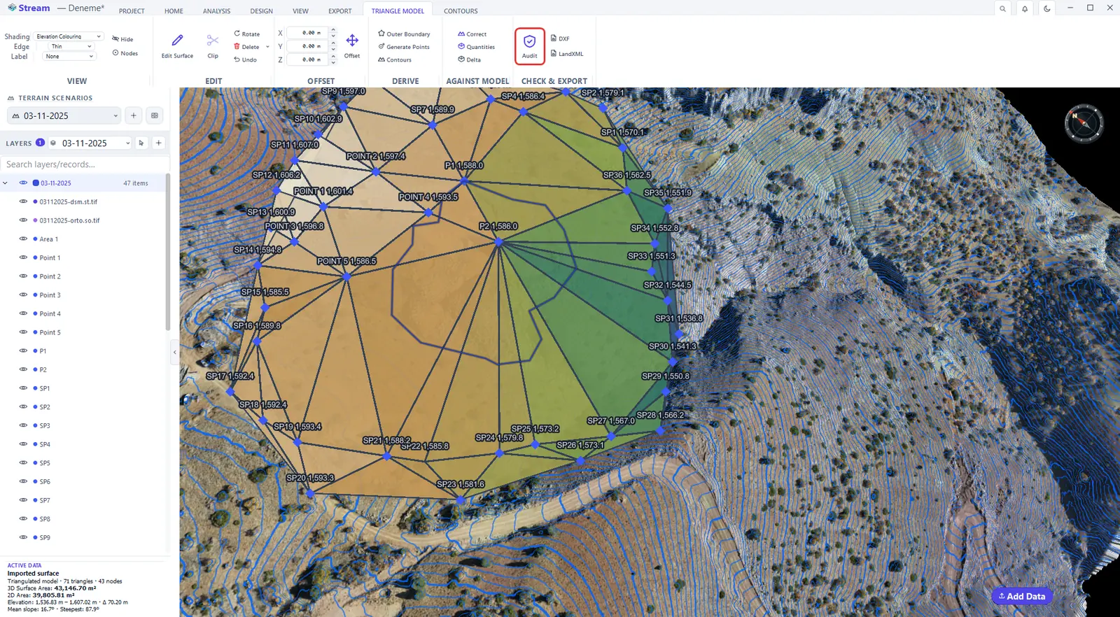
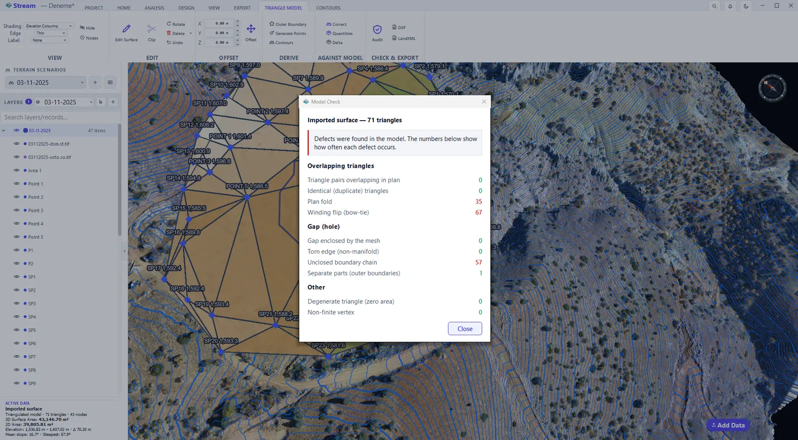
Audit checks the model for errors.
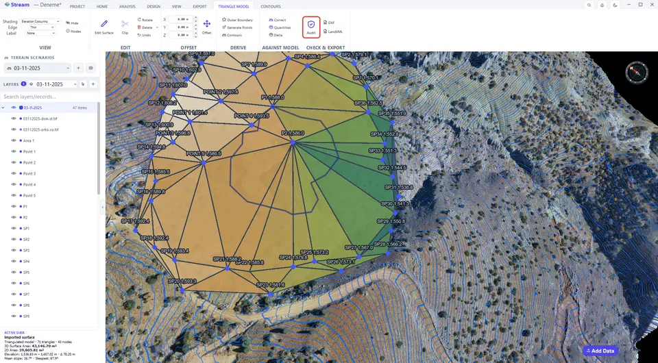
Model check results.
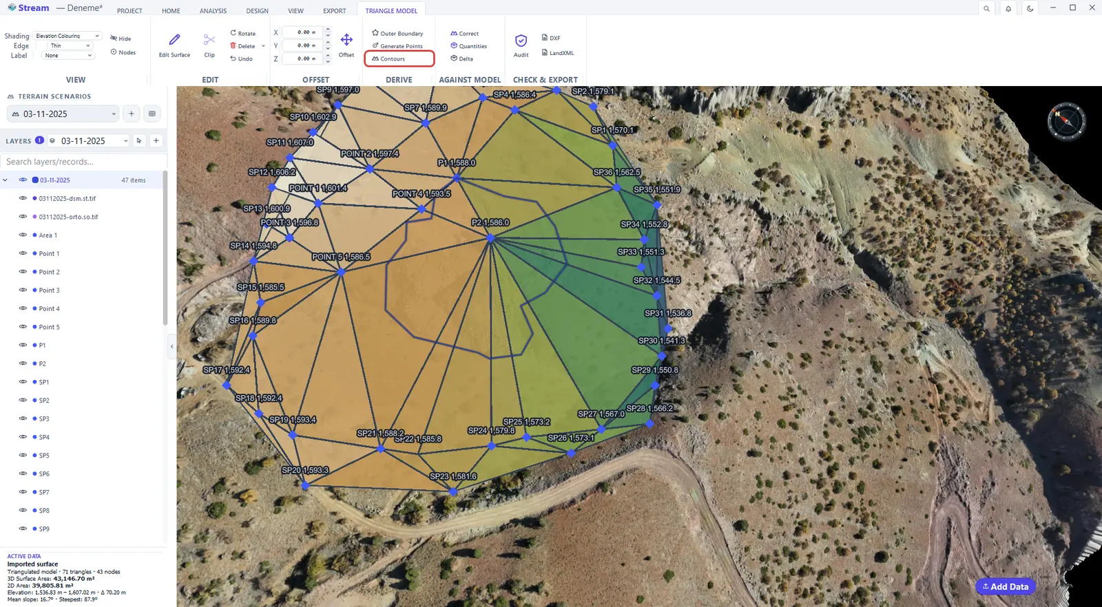
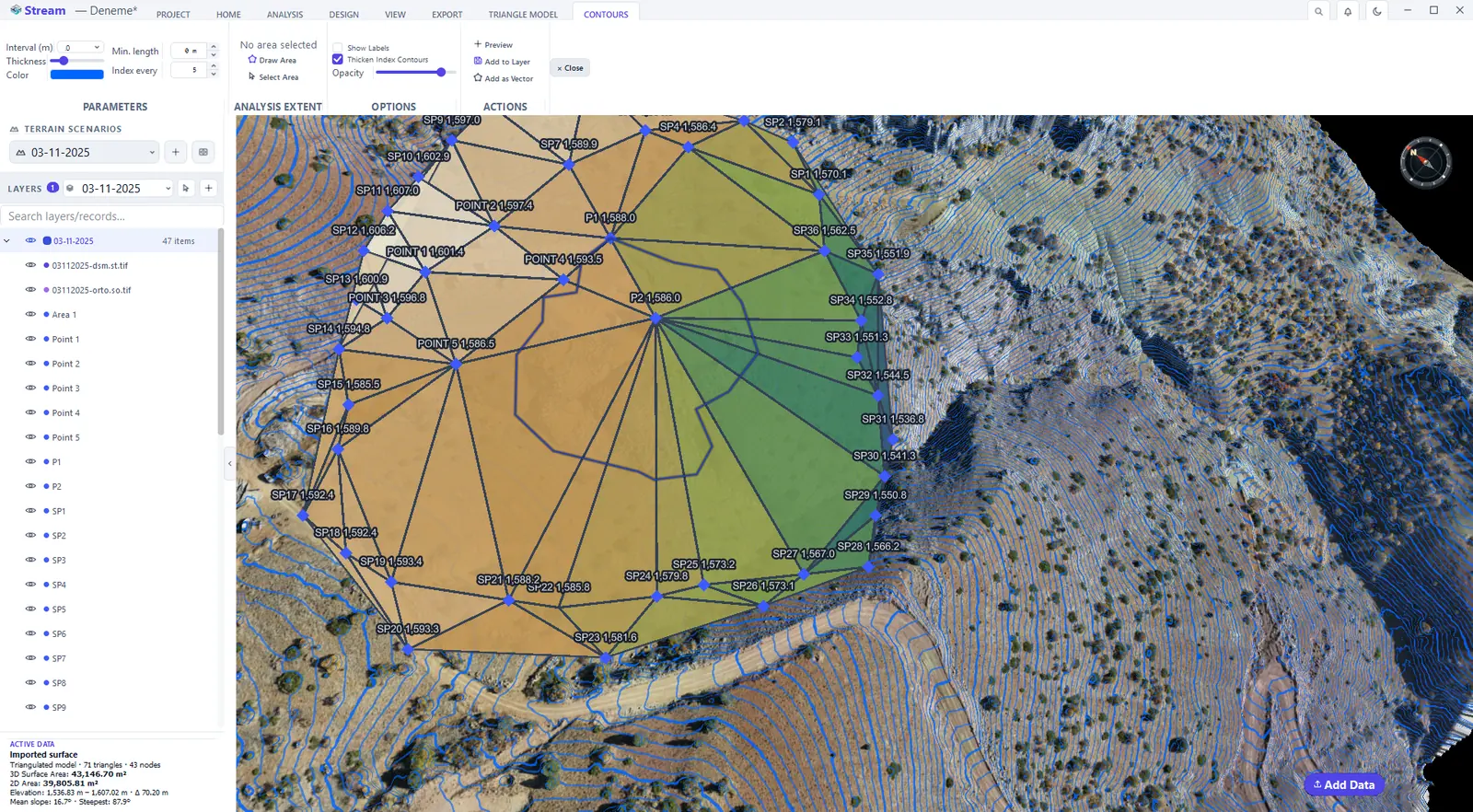
- Contours draws the model's contour lines without needing a DEM.
- Audit runs the Model Check: it counts overlapping triangles, plan folds, winding flips, holes enclosed by the mesh, torn edges, boundary chains that do not close and the number of separate parts. The example surface here was built from a scattered survey list, so the check reports folds and flips along its outline. Repair removes only degenerate, duplicate and overlapping triangles — holes are never filled, because that would mean inventing geometry.
- Clip to Area deletes the triangles outside a selected area; Volume vs Model and Delta compare the surface with the terrain or with a second model as cut and fill.
Drop points to the terrain
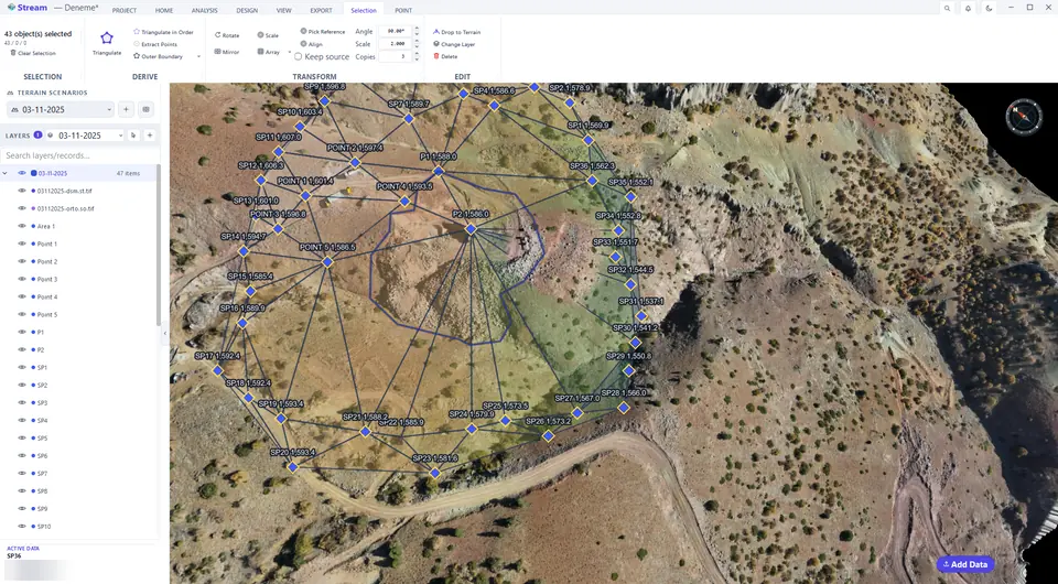
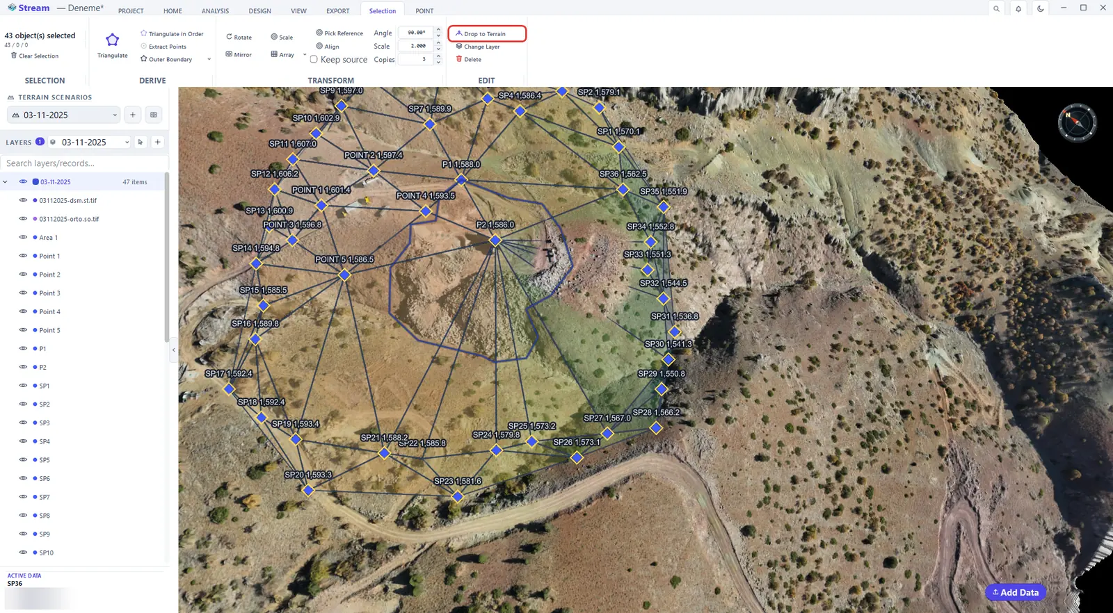
Drop to Terrain sets the selected points onto the terrain surface by snapping their Z to it — useful after points were typed in or imported with approximate elevations.
Select points and press Drop to Terrain.
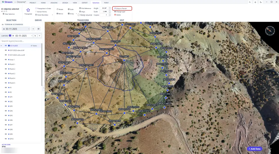
Point elevations now read from the terrain.
Next: Lines.
Related features
What each capability does, which formats it reads and writes, and answers to common questions: