Crest and toe lines
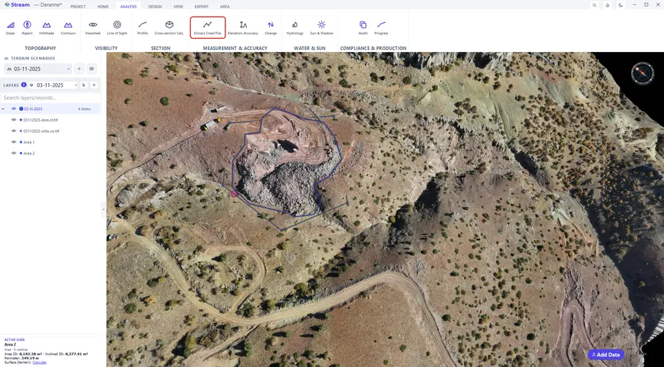
Extract Crest/Toe finds every slope face by itself and adds the crest (top of slope) and the toe (bottom of slope) as 3D lines — hours of CAD work in one command. Click ANALYSIS ▸ MEASUREMENT & ACCURACY ▸ Extract Crest/Toe, choose where it should run, tune the detection and read the result.
Press Extract Crest/Toe on the Analysis tab.
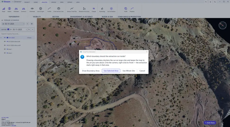
Choose the boundary to search in.
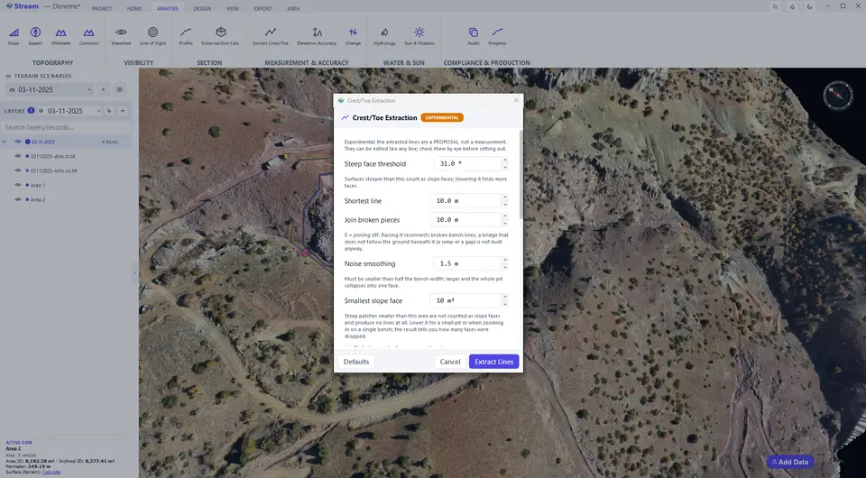
Tune the line detection options.
Crest and toe lines on the pit benches.
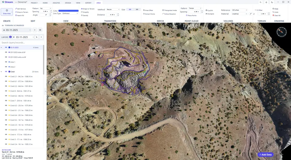
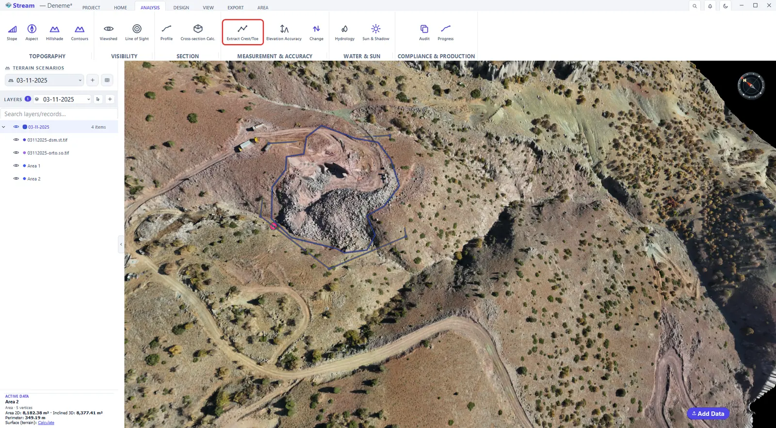
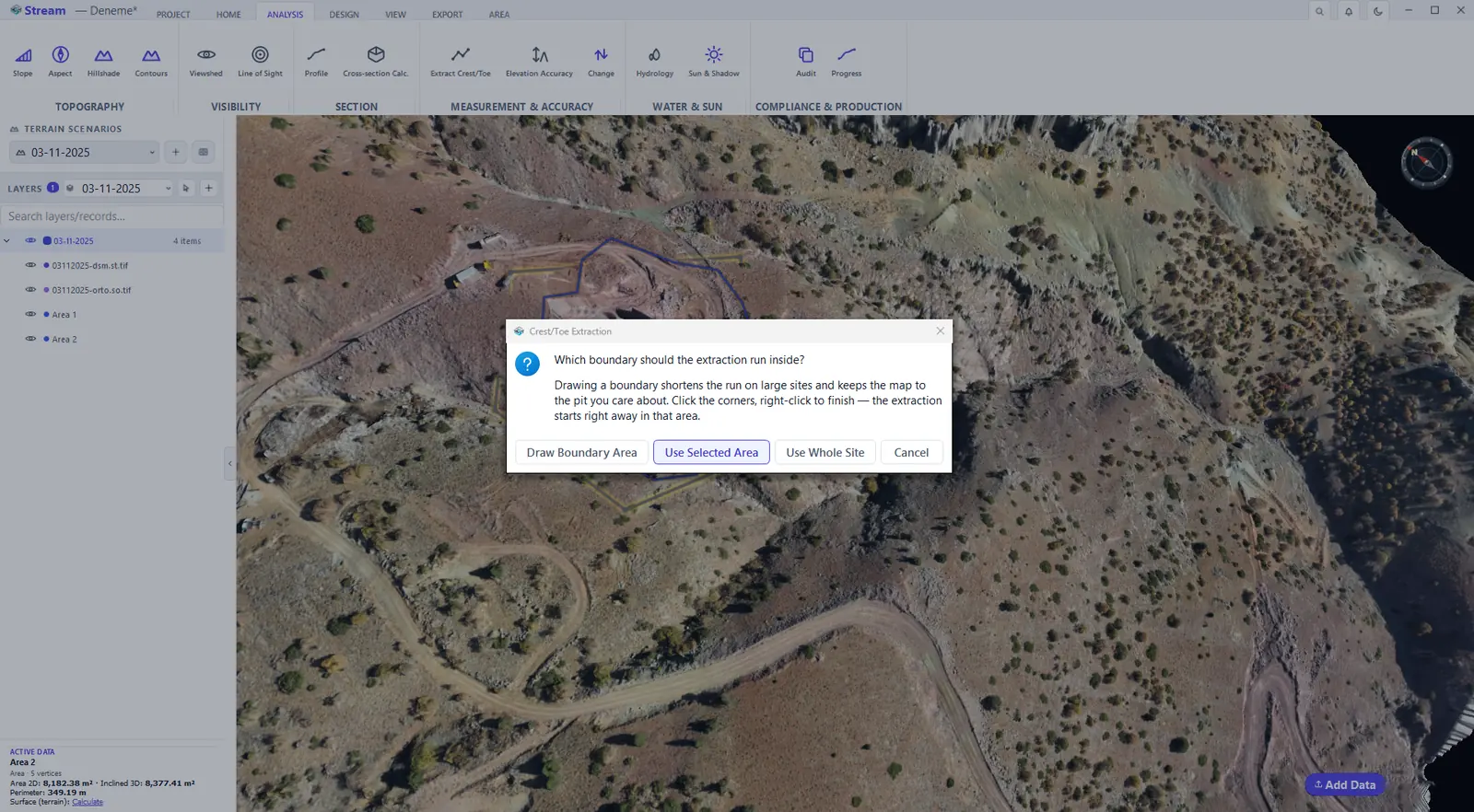
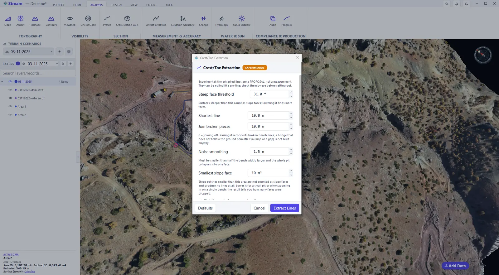
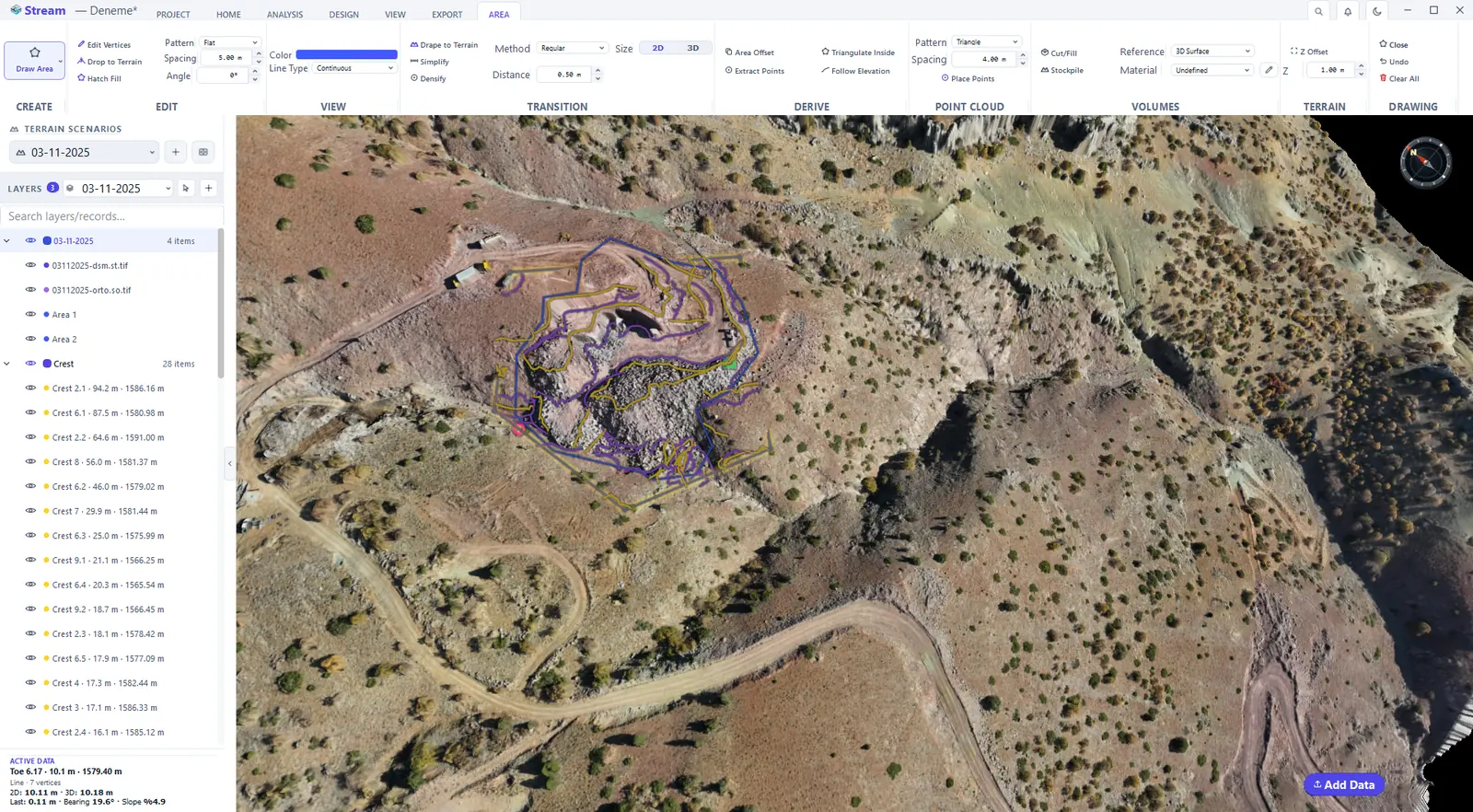
- Where it runs: draw a boundary, use the selected area, or scan the whole map. A smaller area gives a finer result — down to 10 cm cells; the cell size used is reported.
- Output: the lines are written to two layers, Crest and Toe; the layer name is also the DXF layer name. Ramp and haul-road edges are kept apart in Ramp Crest and Ramp Toe, so a road edge is never mistaken for a bench face. Each line is an ordinary line: select it, edit it, undo it, export it to DXF. Crest 3 and Toe 3 are the two edges of the same face.
- Options: the steep-face threshold, the shortest line and the noise-smoothing radius, plus deep search, reject weak breaks and reject texture lines. Lines the engine is less sure of go to grey Low Confidence layers instead of being deleted.
Elevation accuracy
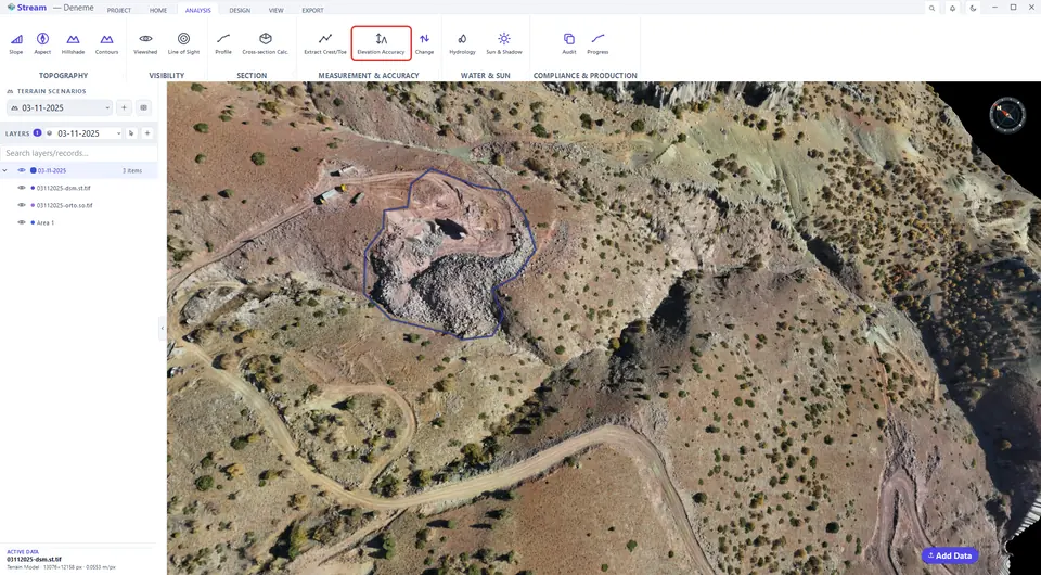
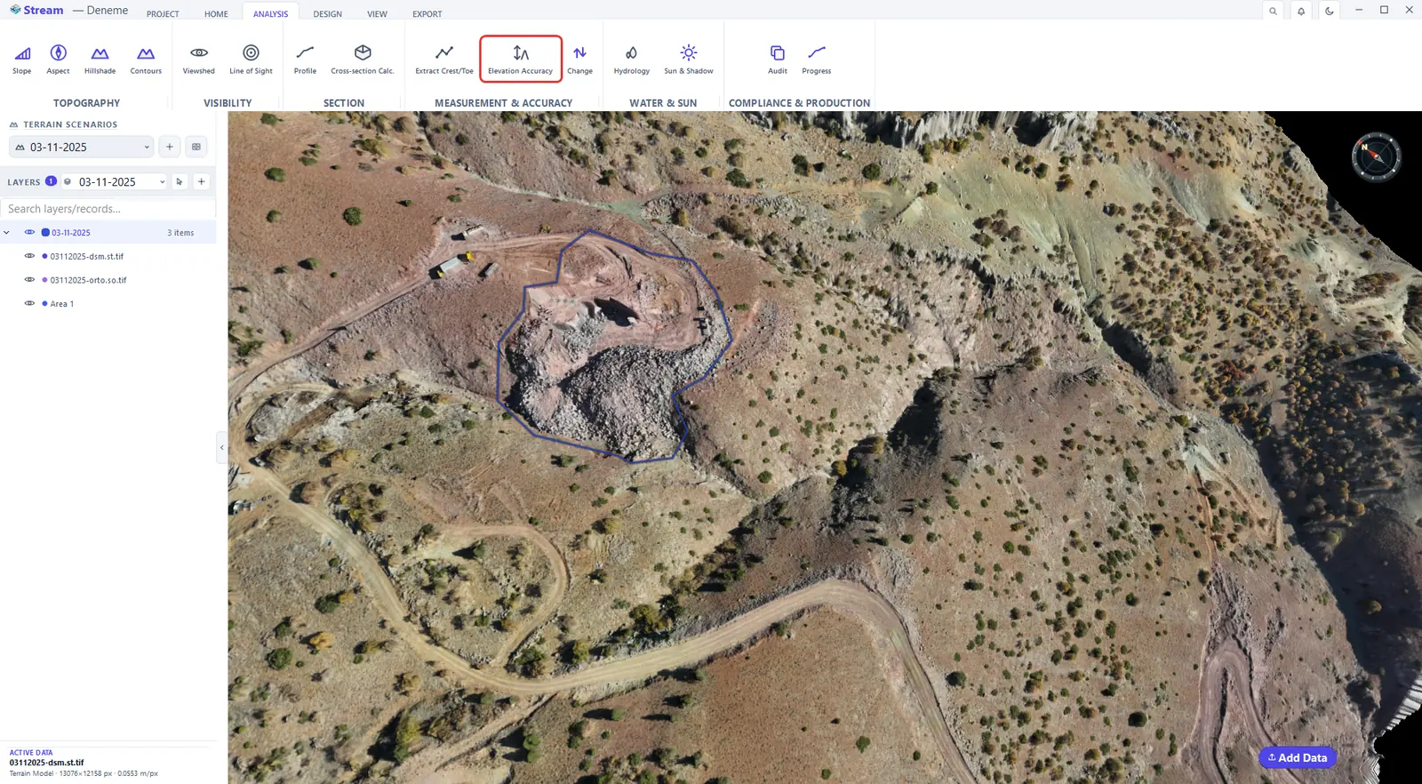
Elevation Accuracy documents how closely a surface matches points of known elevation — ground control points, levelling or GNSS measurements. Click ANALYSIS ▸ MEASUREMENT & ACCURACY ▸ Elevation Accuracy: the panel opens under the view.
Press Elevation Accuracy on the Analysis tab.
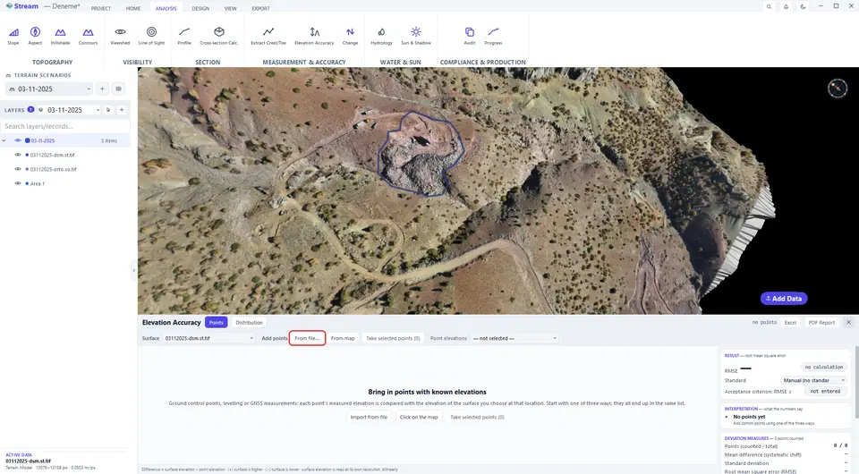
Choose the surface and press From file.
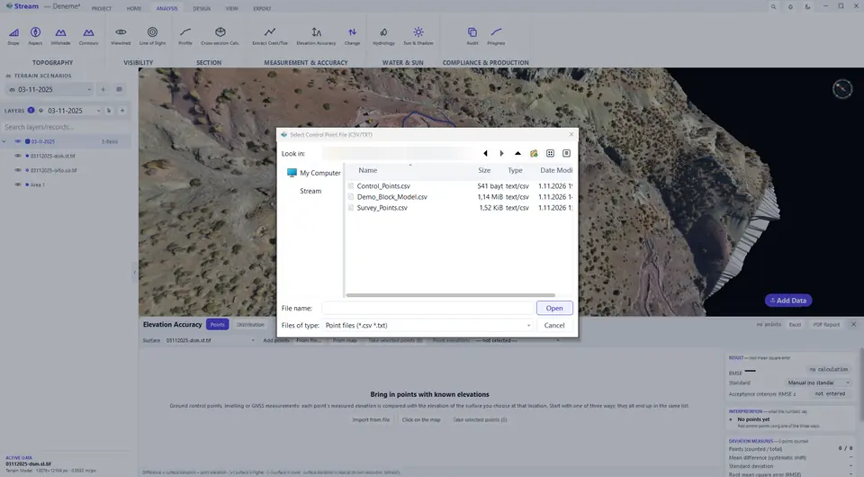
Pick the control points file.
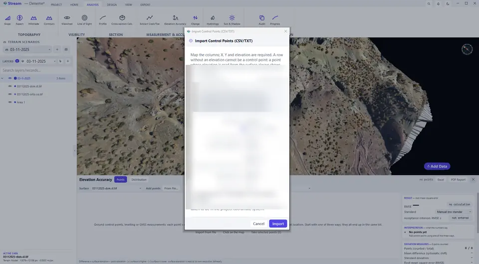
Match the columns of the file.
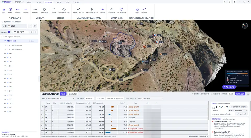
RMSE and residuals for every control point.
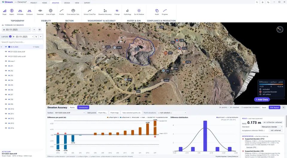
Distribution of the residuals.
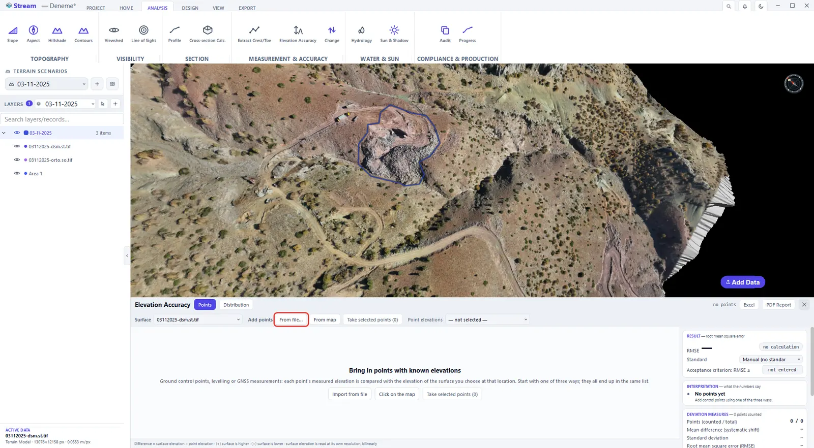
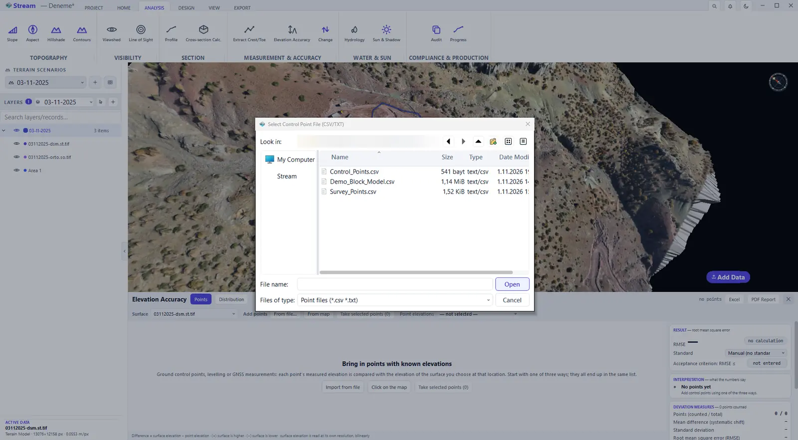
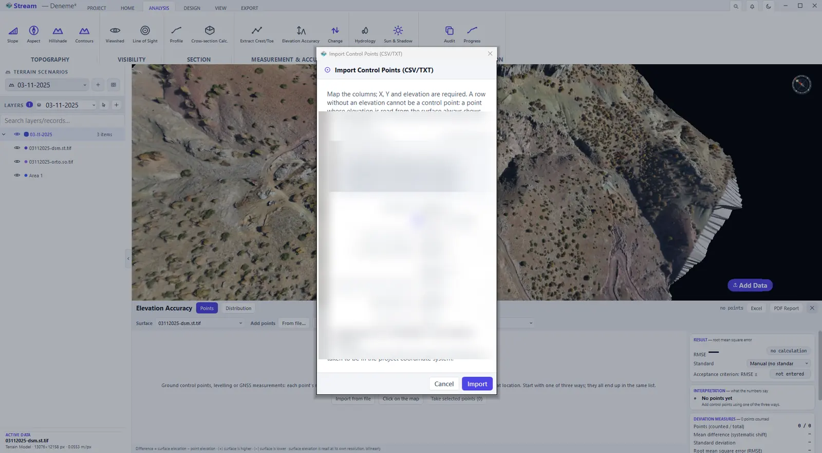
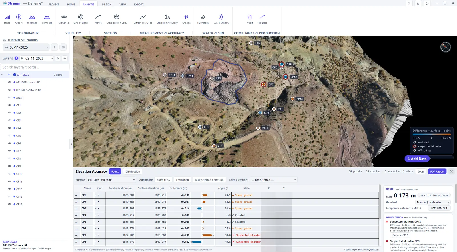
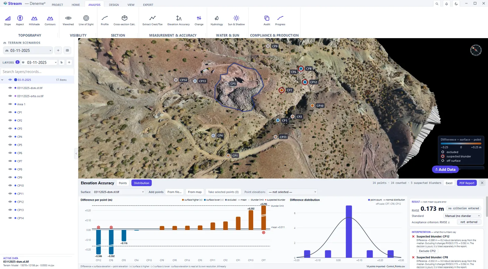
- Surface — choose the surface the points are compared against first. Nothing is computed until you do.
- Bring in the points — From file… (a CSV or TXT file with the name, X, Y and the measured elevation; map the columns in the import window), From map (click and type the measured elevation) or Take selected points.
- Read the result — for every point the panel shows surface elevation − point elevation and summarises the result as RMSE, with the mean difference, standard deviation and 95 % accuracy. On the map each point is marked in the colour of its difference. A point far from the others is flagged as a suspected blunder but never removed on its own. Enter an acceptance criterion to get a pass or fail verdict.
- Distribution — the second tab plots the differences point by point and as a distribution.
- Excel and PDF Report write the table and the report.
Coordinate transformation
Coordinate Transformation moves the whole project — points, lines, areas, text, rasters and terrain corrections together — into another coordinate system. Click HOME ▸ COORDINATE SYSTEM ▸ Coordinate Transformation. The flow is always the same: Method → Calculate → check Scope → Apply.
Press Coordinate Transformation.
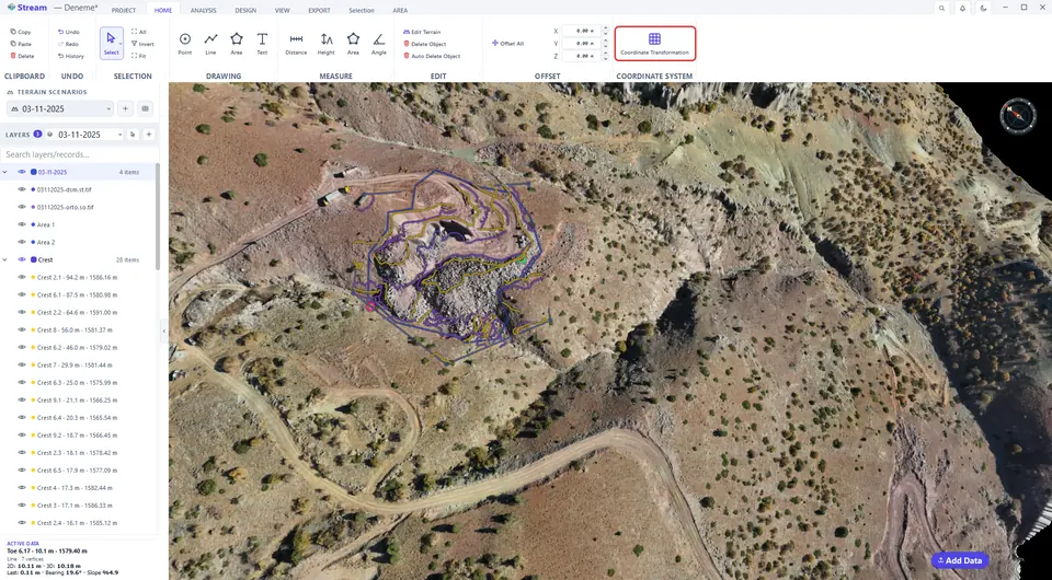
Choose how to define the transformation.
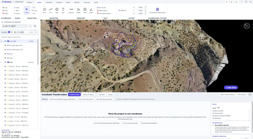
Method: From common points.
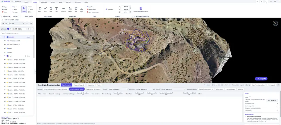
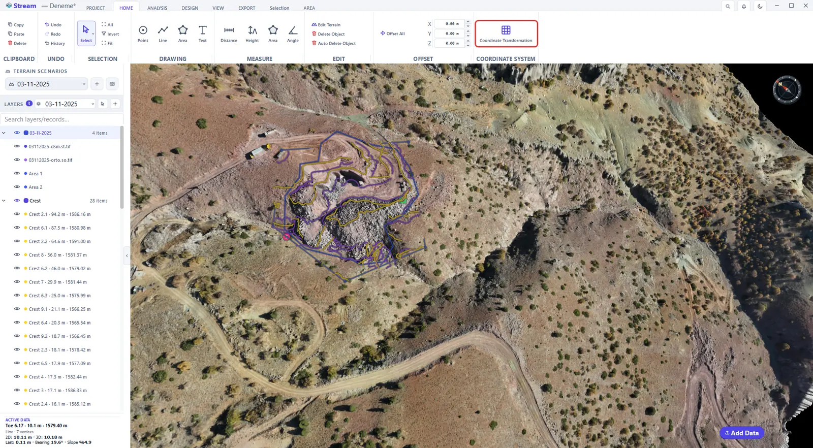
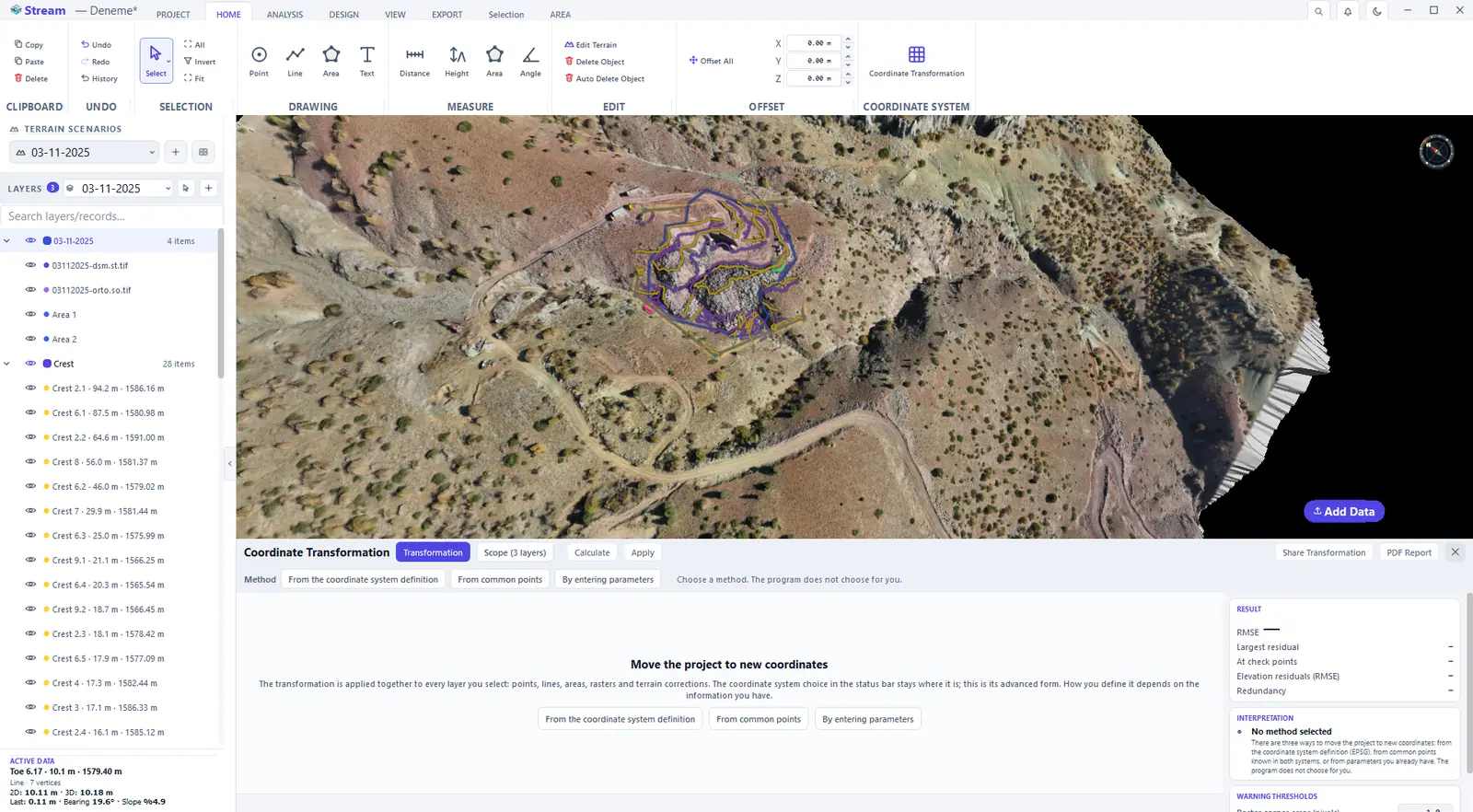
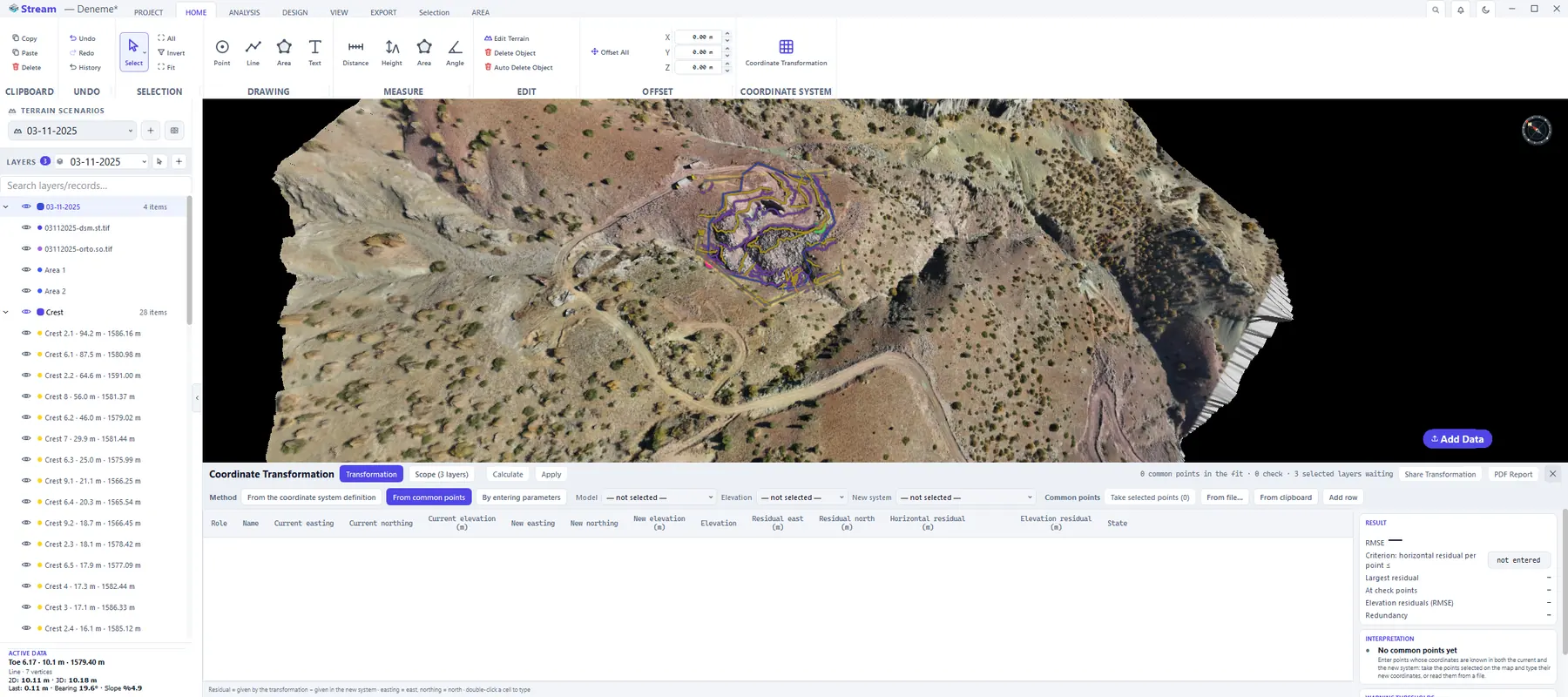
Choose the Method; the box opens with — not selected — because STREAM never chooses for you:
- From the coordinate system definition — both systems are known (EPSG); you pick the target.
- From common points — for a local grid or an old datum: the transformation is built from points known in both systems. Add the points from the map, from a file or the clipboard, or by hand; each point is Counted, Check or Excluded.
- By entering parameters — a shift, with optional rotation, scale and elevation shift, that someone gave you as numbers.
Press Calculate and read the result: residuals and RMSE for the common points, a model comparison (shift, similarity, affine) and an interpretation card that states the findings in plain sentences. Check the Scope — which layers are transformed — then press Apply; Undo restores the data exactly. Share Transformation and PDF Report document it.
To change only the coordinate system the project is displayed in, click the Project CRS indicator at the bottom-left of the status bar and pick a system from the list.
Edit the terrain
The EDIT and OFFSET groups on the HOME tab change the data itself. Edit Terrain adjusts surface elevations by hand.
Press Edit Terrain.
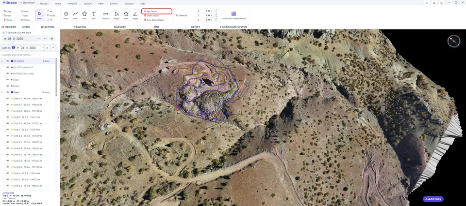
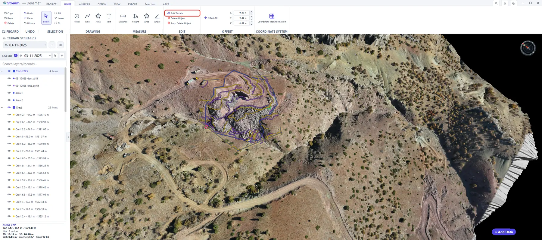
These edits are kept as records in LAYERS: toggle the eye to compare the surface with and without them. Z Offset on the AREA tab raises or lowers the terrain inside a selected area (Areas).
Delete an object from the terrain
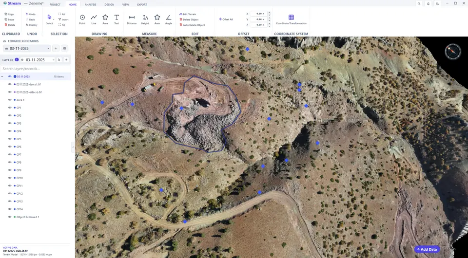
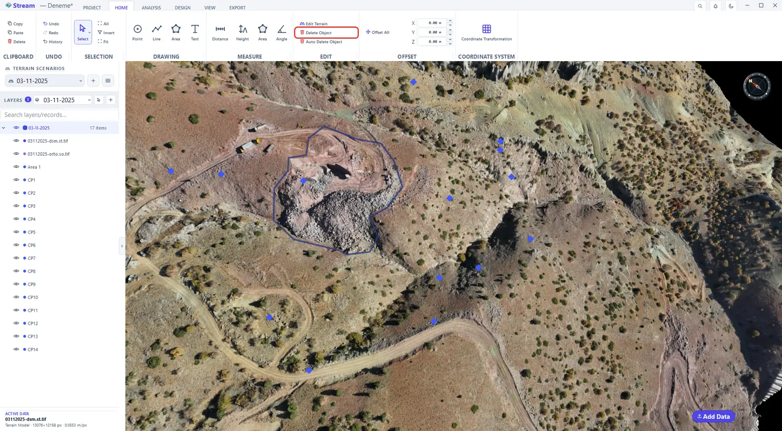
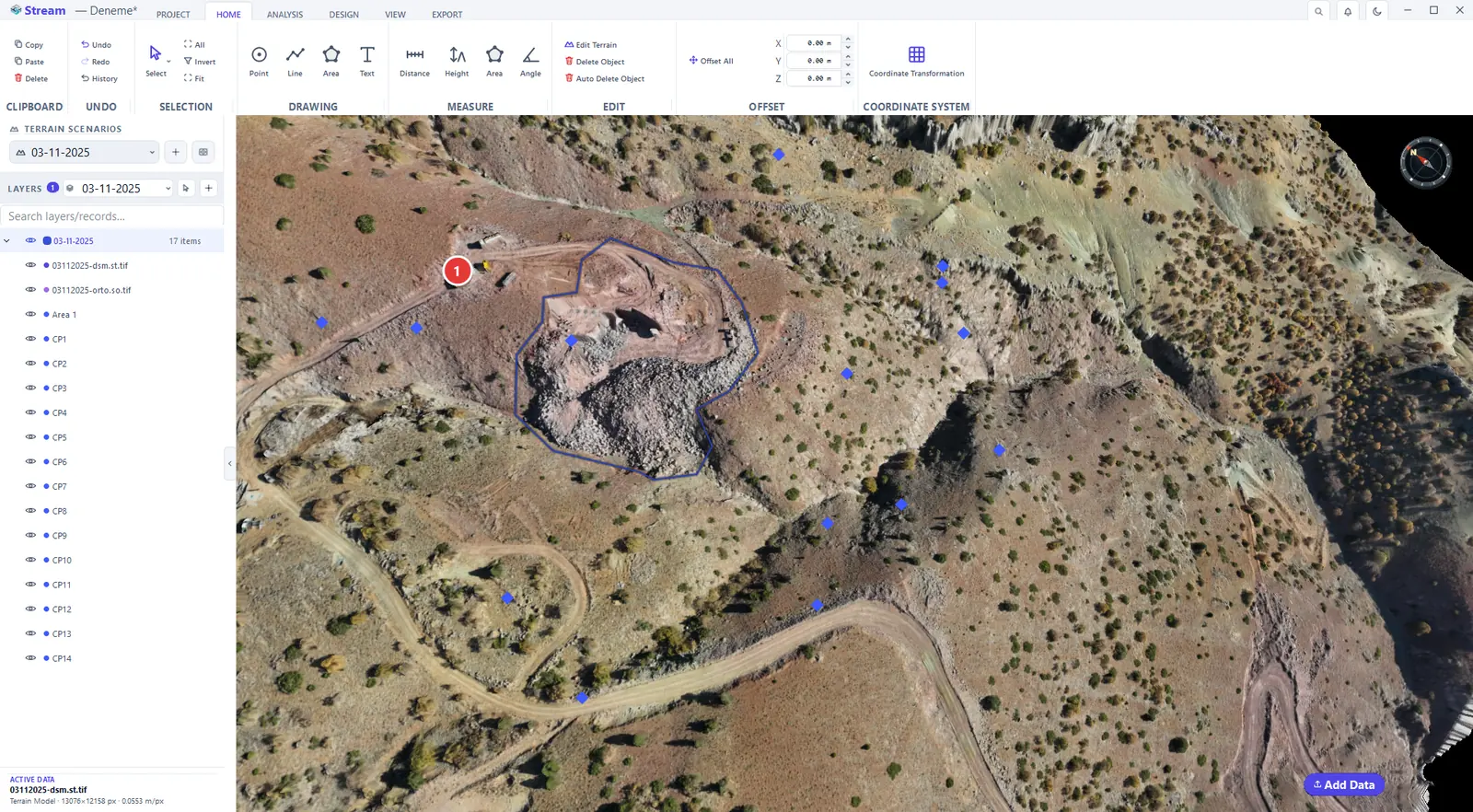
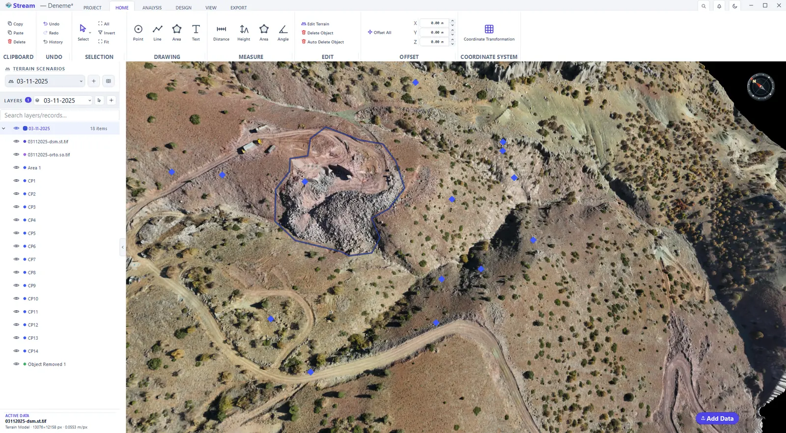
Delete Object removes unwanted objects from the terrain surface one by one. Press it, then click the object on the terrain. The surface is rebuilt without it, and the edit is kept as an Object Removed record in LAYERS: toggle its eye to compare the surface with and without it.
Press Delete Object.
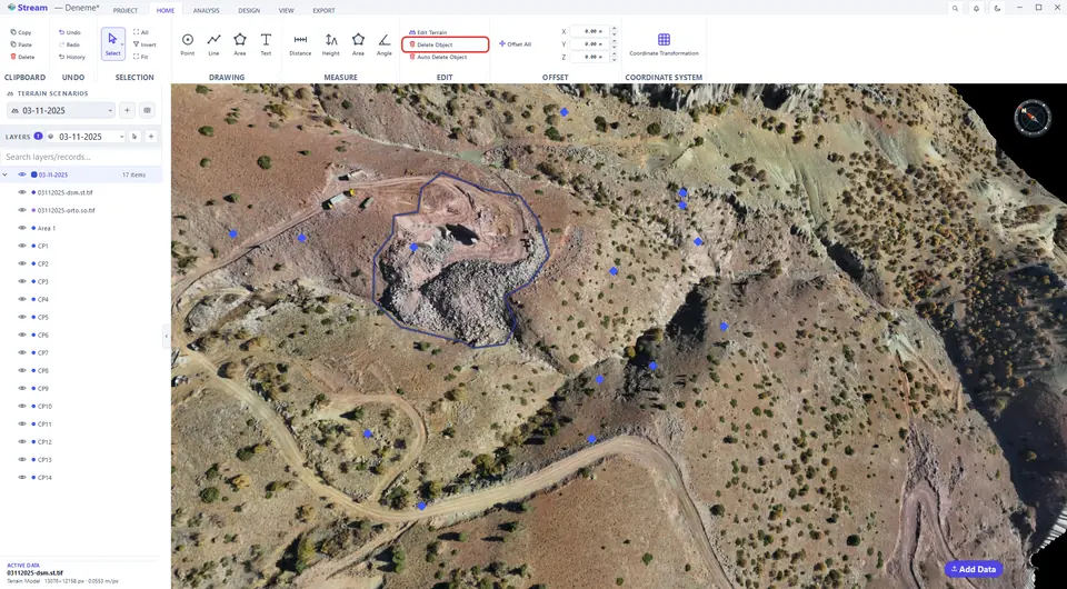
Click the object on the terrain.
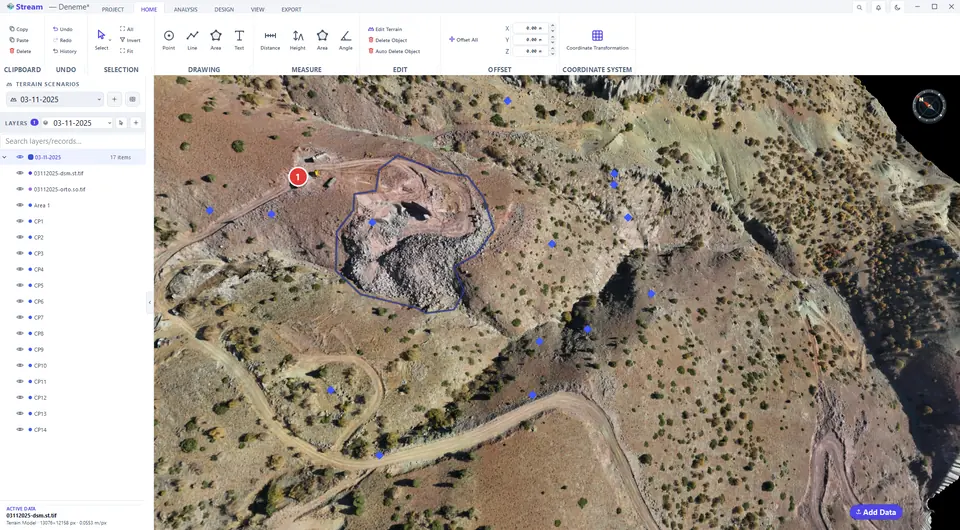
The object is removed from the terrain surface.
Delete objects automatically
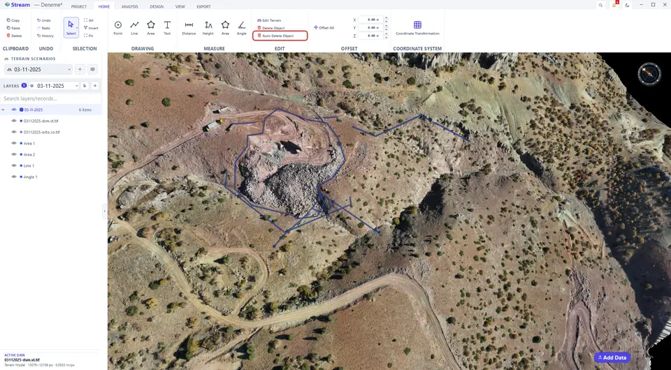
Auto Delete Object clears every object inside an area you draw, one area after another (right-click ends the tool).
Press Auto Delete Object.
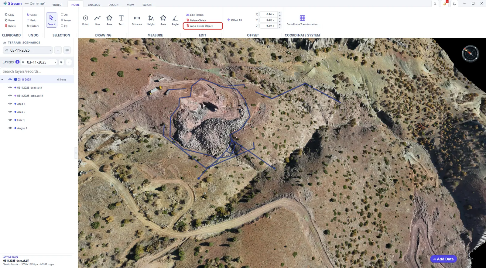
Offset all coordinates
Offset All shifts every coordinate by the X, Y and Z values next to it — reversibly: the data itself stays in place, the shift is reflected in all on-screen and exported coordinates.
Enter X, Y and Z shifts, press Offset All.

Import a LAS or LAZ point cloud
Press Add Data and pick a LAS or LAZ file. The cloud is not taken in as it is — you decide what is produced:
Press Add Data and pick a LAS or LAZ file.
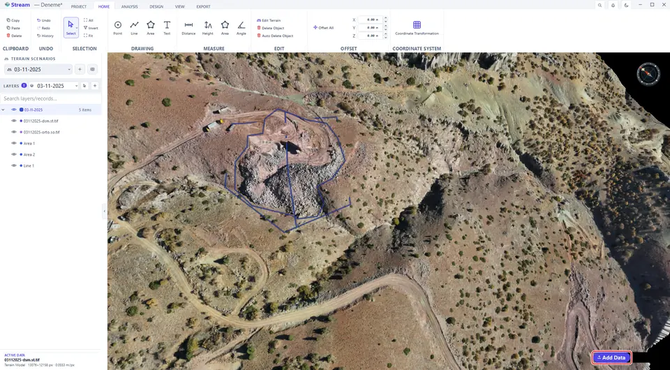
Choose the point cloud.
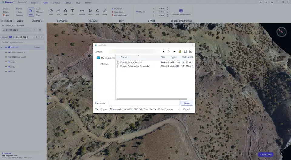
Build a DEM and an orthophoto from the cloud.
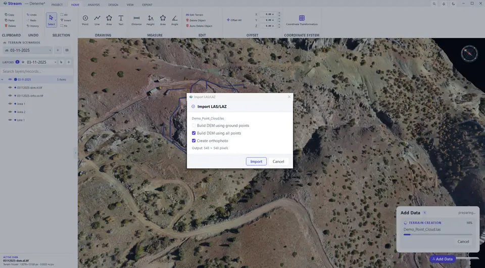
The cloud becomes a new terrain in the project.
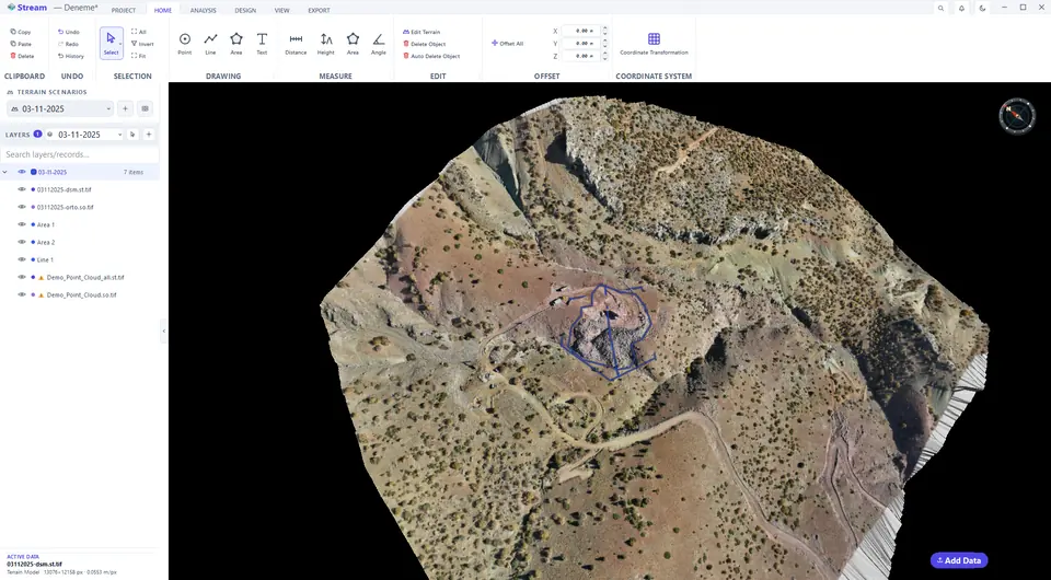
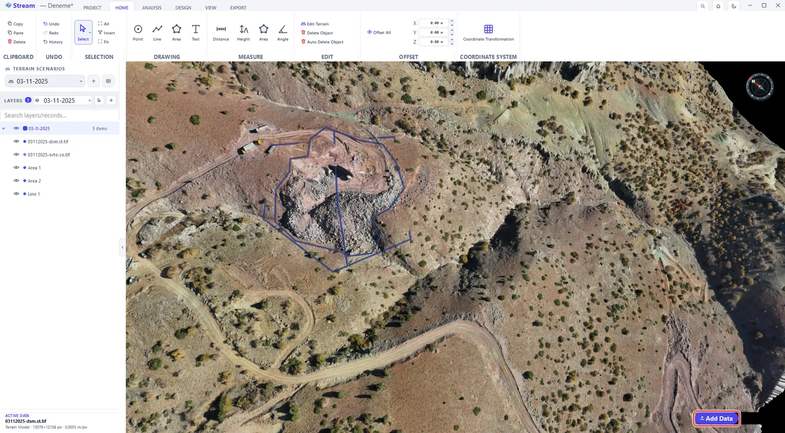
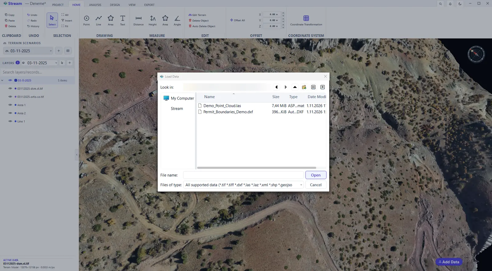
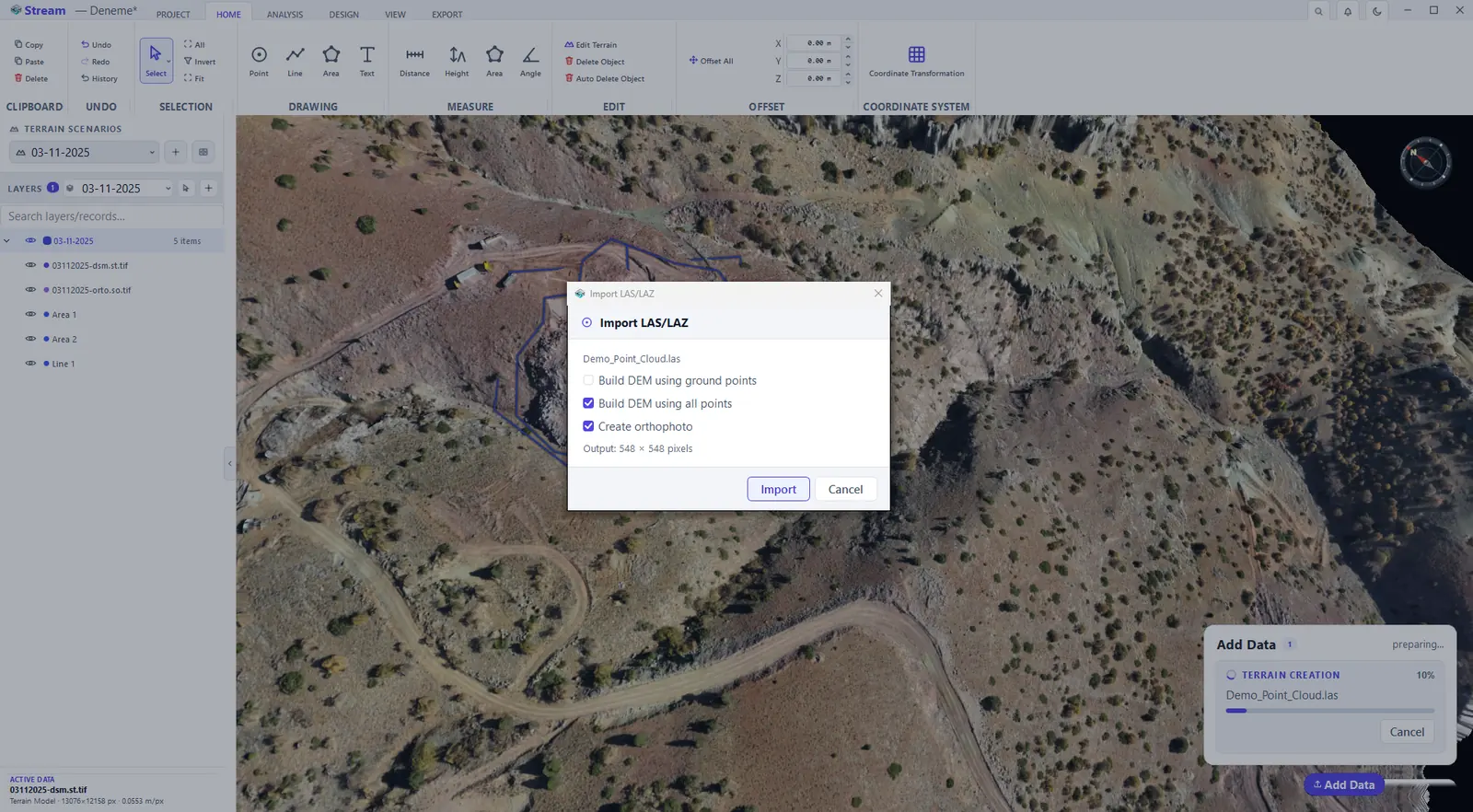
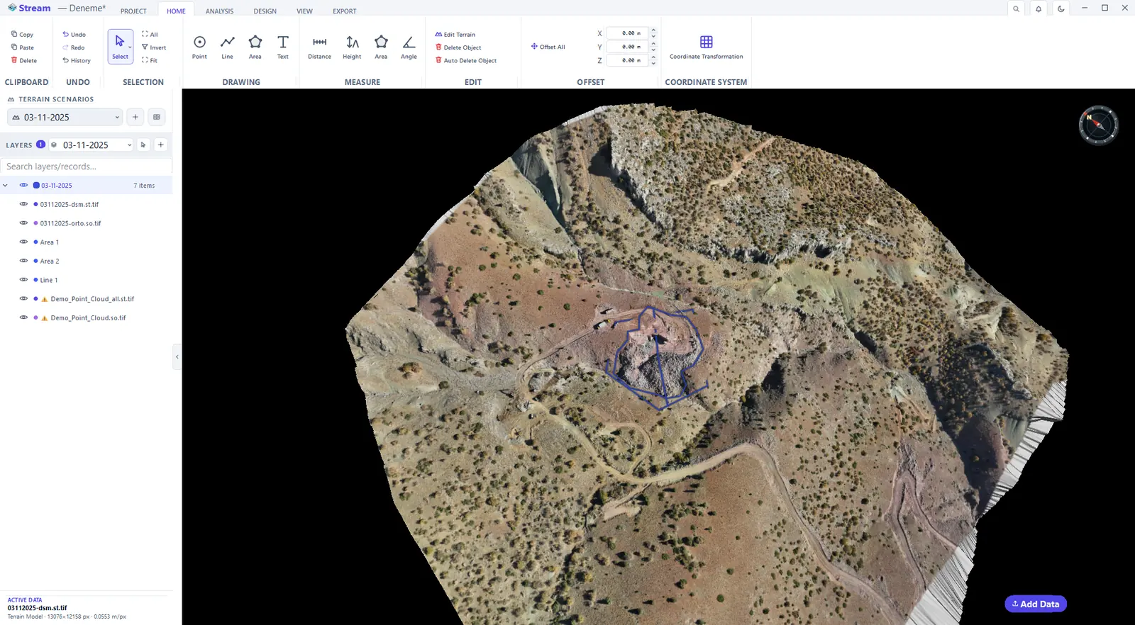
- Build DEM from ground points — the terrain from ground-classified points only, so trees and buildings do not enter the surface. If the file has no classified ground points the option is disabled and says why.
- Build DEM from all points — uses every point; the surface then includes vegetation and structures.
- Build orthophoto — makes an image from the points' colour (RGB); disabled when there is no colour.
- Resolution (m/pixel) — the output cell size. The suggestion is computed from the point density, and the dialog reports the pixel size it will produce.
Import stays disabled until you choose at least one output. The file is then prepared in a card at the bottom-right of the view; when it says the data is ready, press Add.
Next: Road and corridor design.
Related features
What each capability does, which formats it reads and writes, and answers to common questions: