
Import a block model CSV
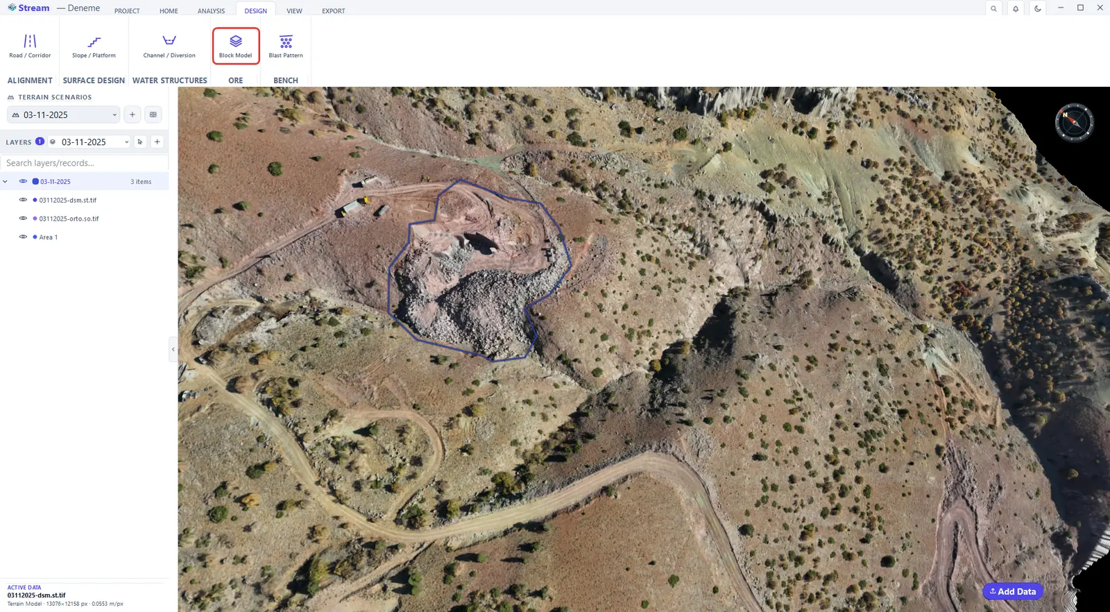
Open it from DESIGN ▸ ORE ▸ Block Model. The module does not build a block model and does not estimate grade: it imports the table that came out of drilling and grade estimation in another package, intersects it with the terrain and with the pit design, and gives you the ore and waste split, tonnage bench by bench and the classification breakdown.
Press Block Model on the Design tab.
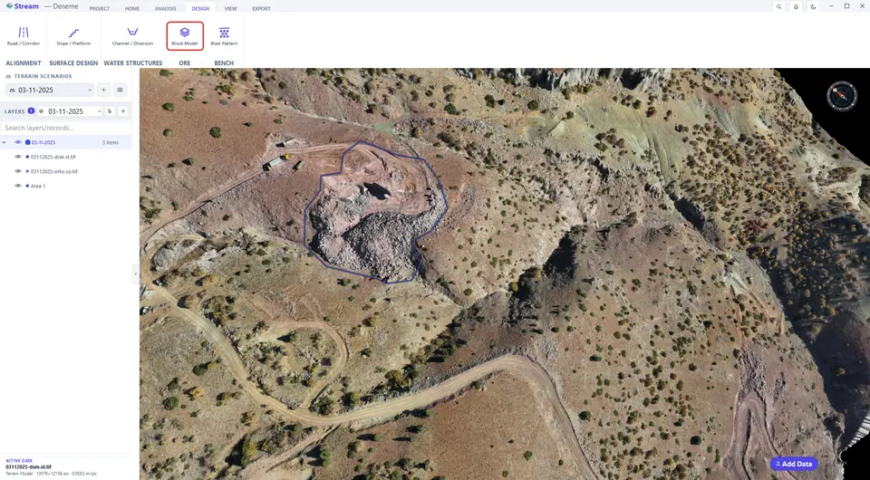
Import a block model CSV.
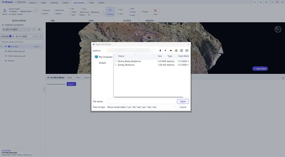
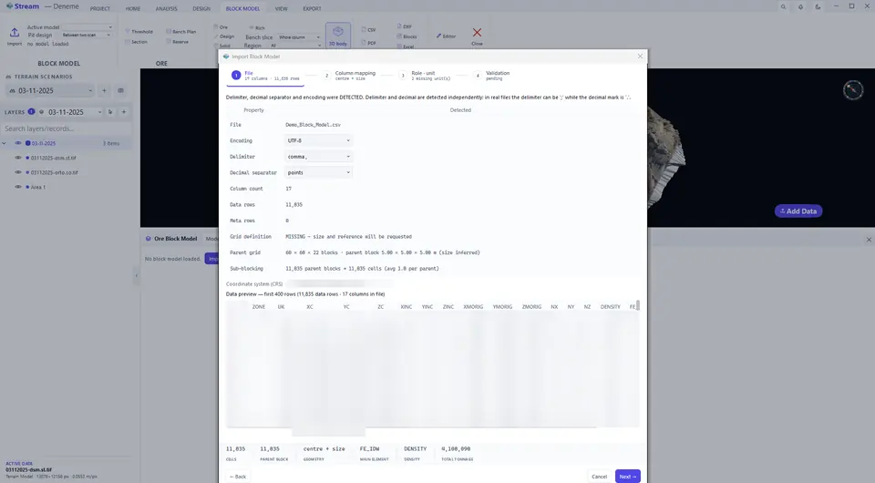
Read the file and detect its format.
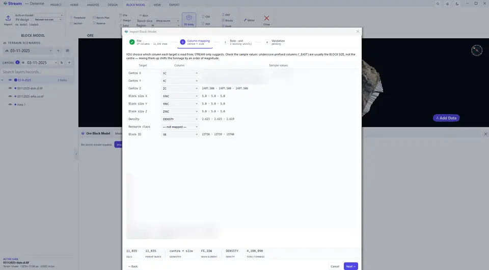
Match the columns.
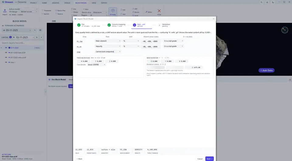
Choose roles and units.
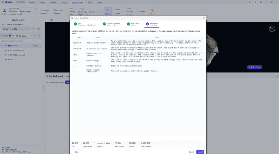
Validate and import.
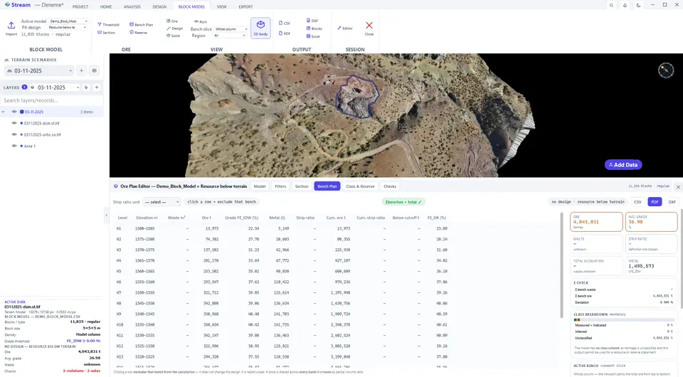
The model is loaded with its summary.
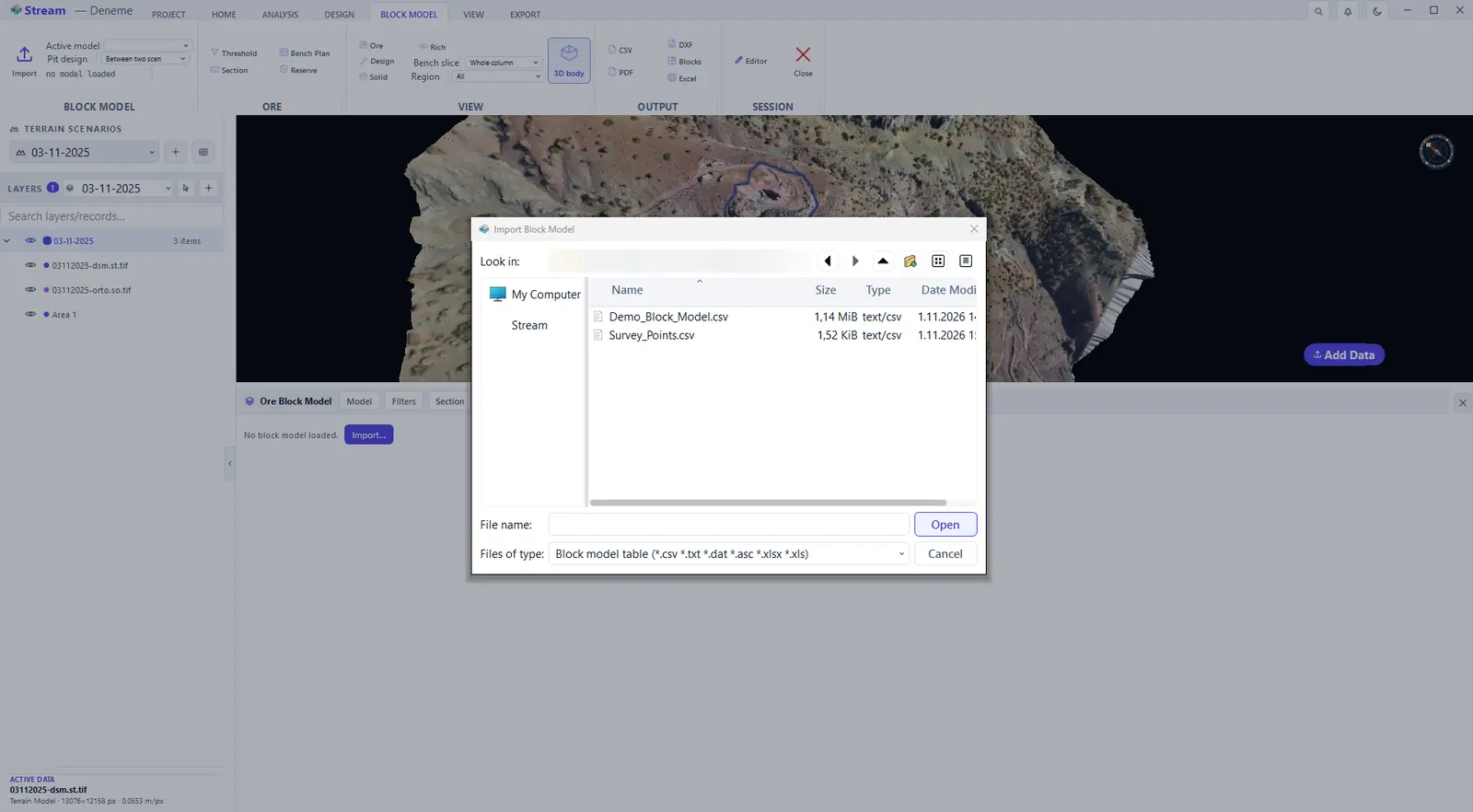
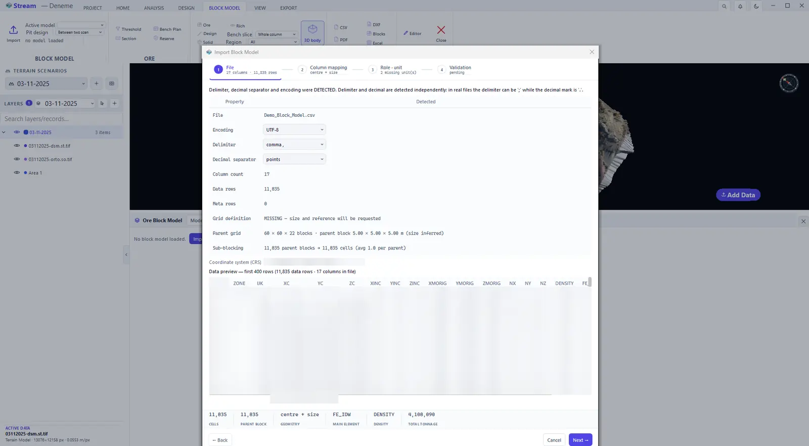
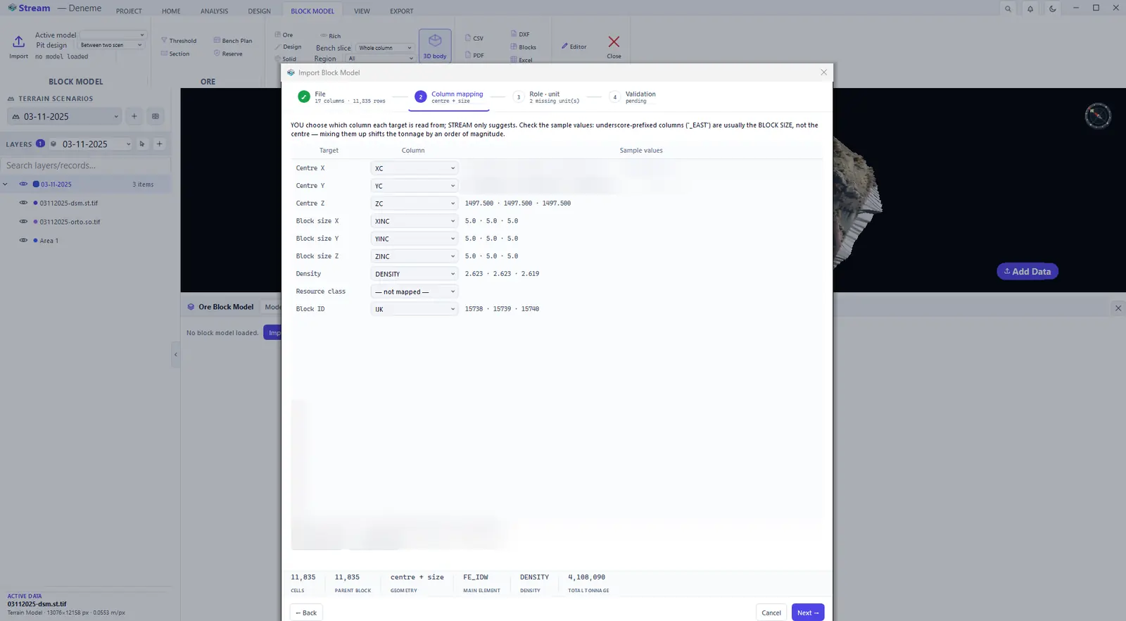
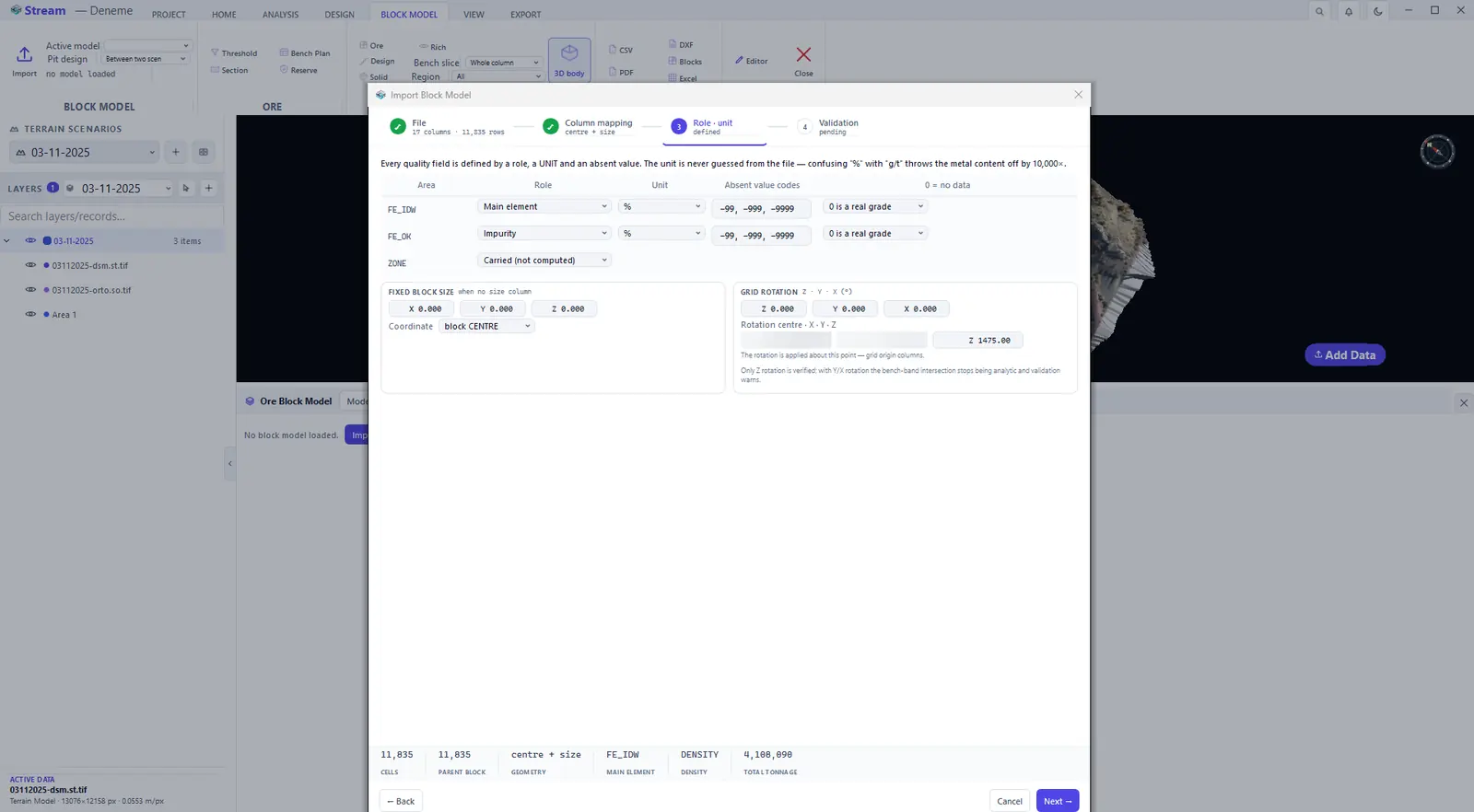
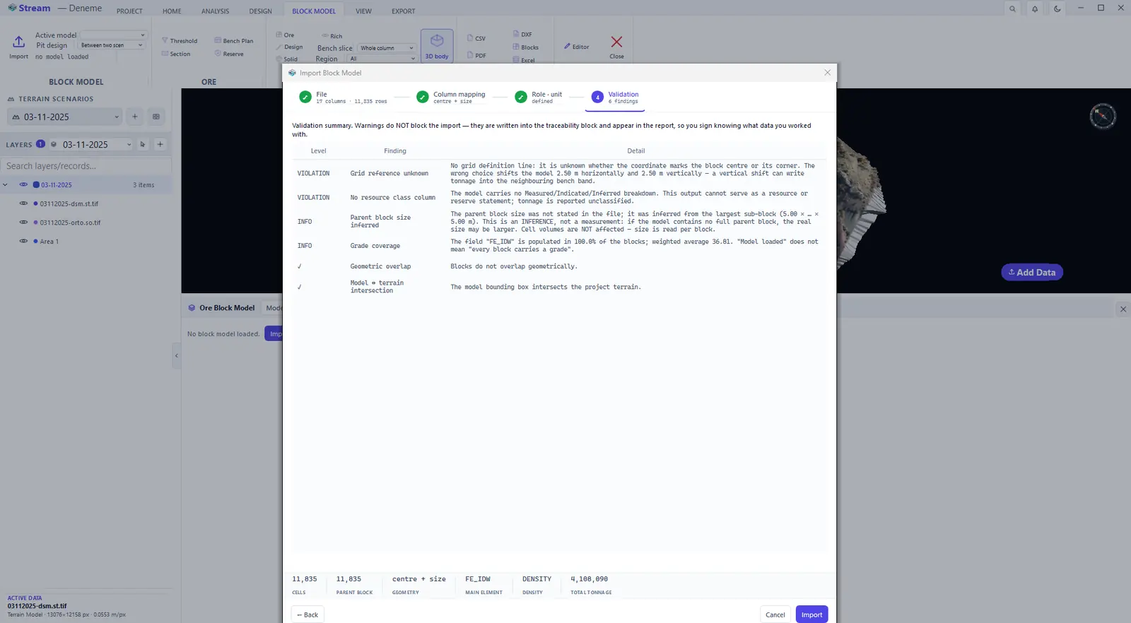
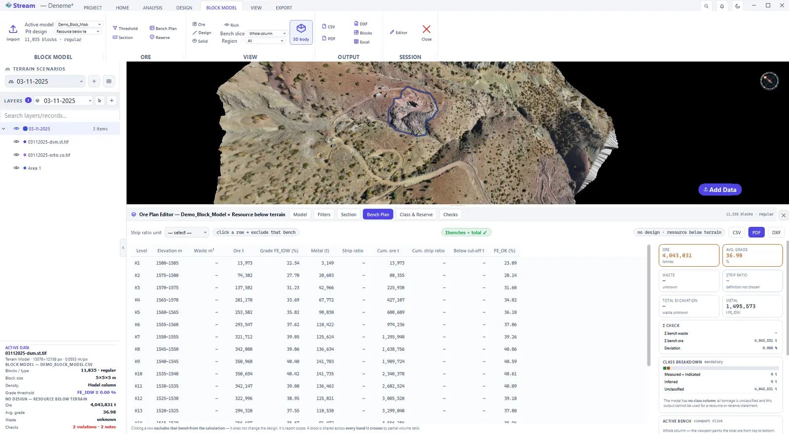
Import… opens a four-step wizard: File (delimiter, decimal separator and encoding are detected, you confirm) → Column mapping (guessed, confirmed by you) → Role · unit → Validation. There are two gates and they work in opposite directions: you cannot pass without choosing the unit — that is where a silent ten-thousandfold tonnage error comes from — but validation warnings do not block the import, so you sign off knowing how dirty the data is. A block model file carries no coordinate system and it cannot be guessed; you state it.
Read the model: the six tabs
The BLOCK MODEL ribbon tab carries the ORE, VIEW and OUTPUT groups, and once a model is loaded the editor under the view has six tabs:
Model tab.
Filters tab.
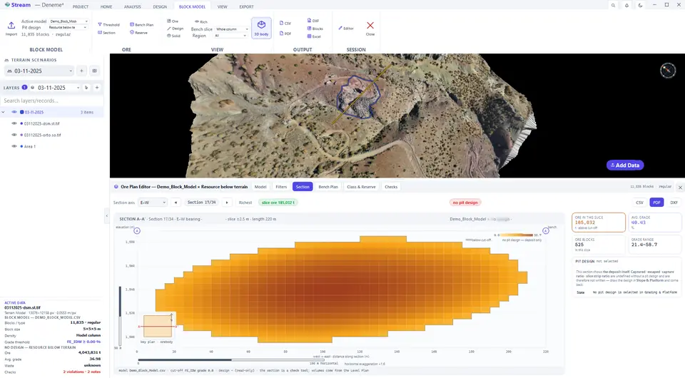
Section tab.
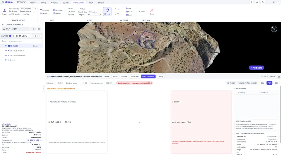
Class & Reserve tab.
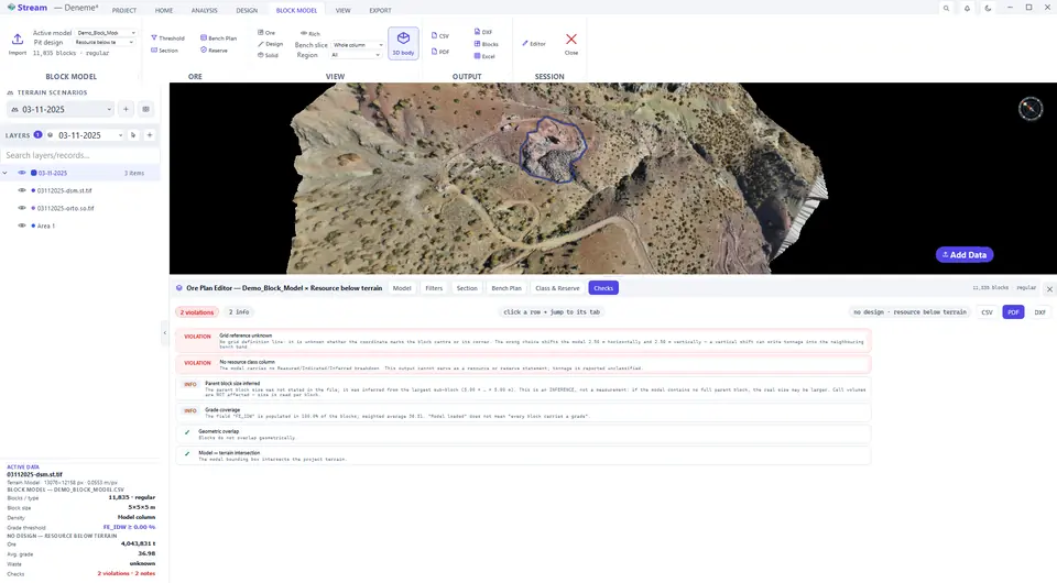
Checks tab.
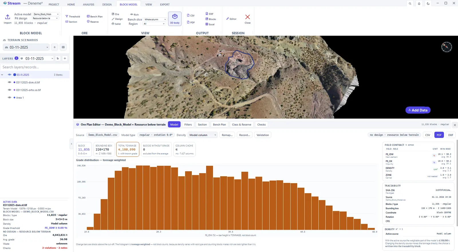
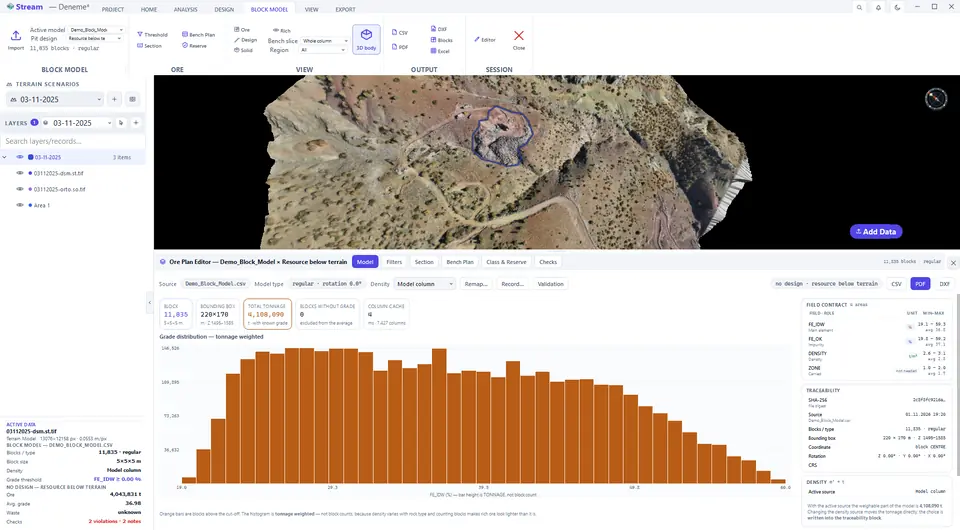
- Model — the identity of the model: block size and grid, the fields, the grade distribution (tonnage weighted), the traceability block (file, SHA-256 and time of import) and where the density comes from.
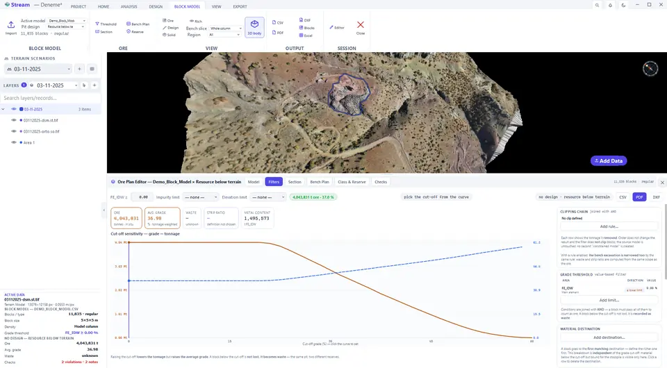
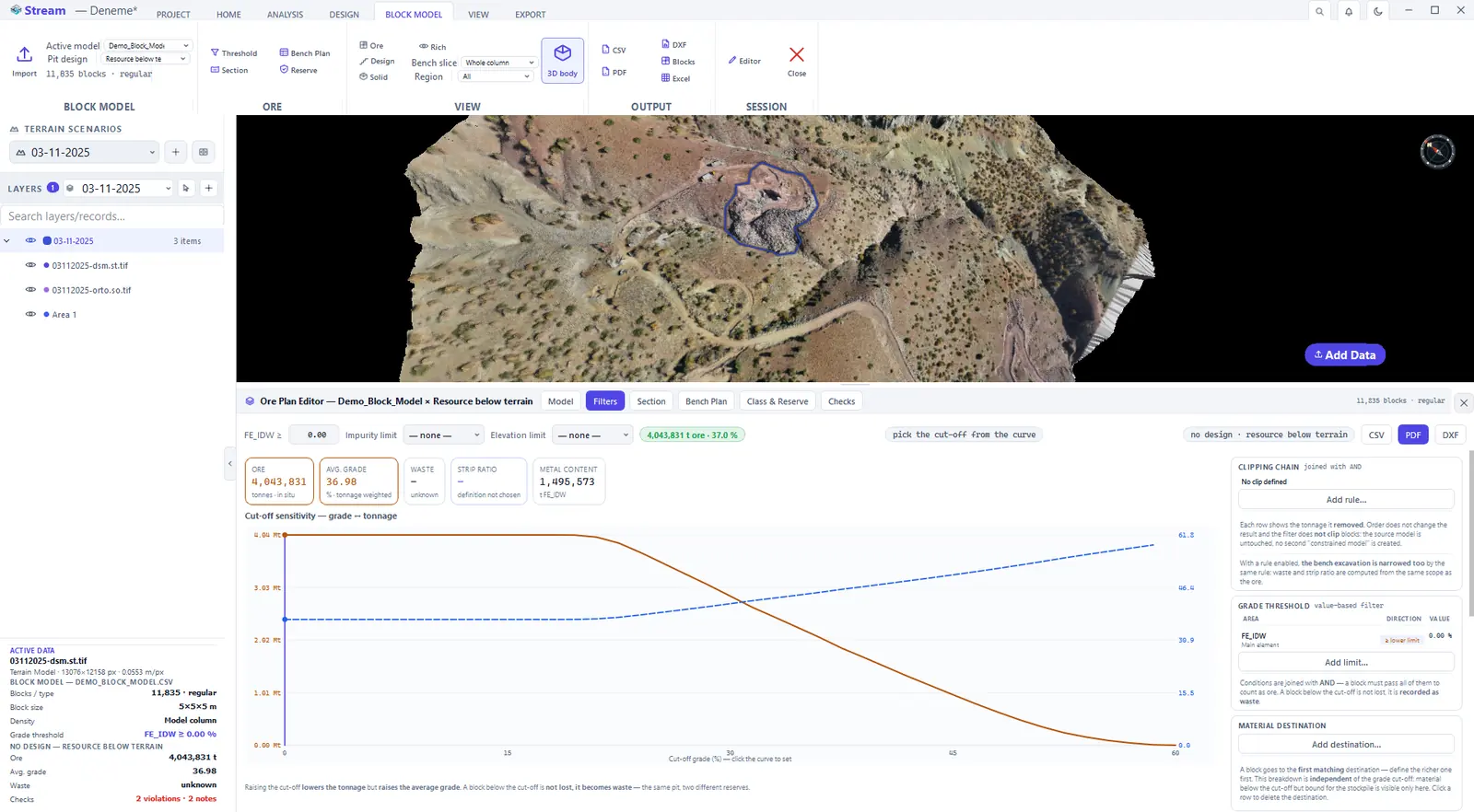
- Filters — the grade cut-off. Raising it lowers the tonnage but raises the average grade; a block below the cut-off is not lost, it goes to waste — the same pit, two different reserves. The cut-off sensitivity curve plots grade against tonnage, and rules and material destinations refine it.
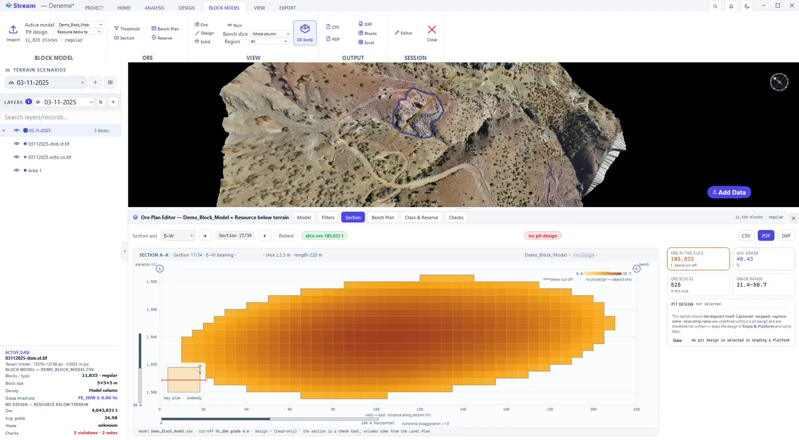
- Section — where the model, the ground and the pit design meet: a section through the deposit with the blocks coloured by grade.
- Bench Plan — tonnage and average grade per bench band, with cumulative columns.
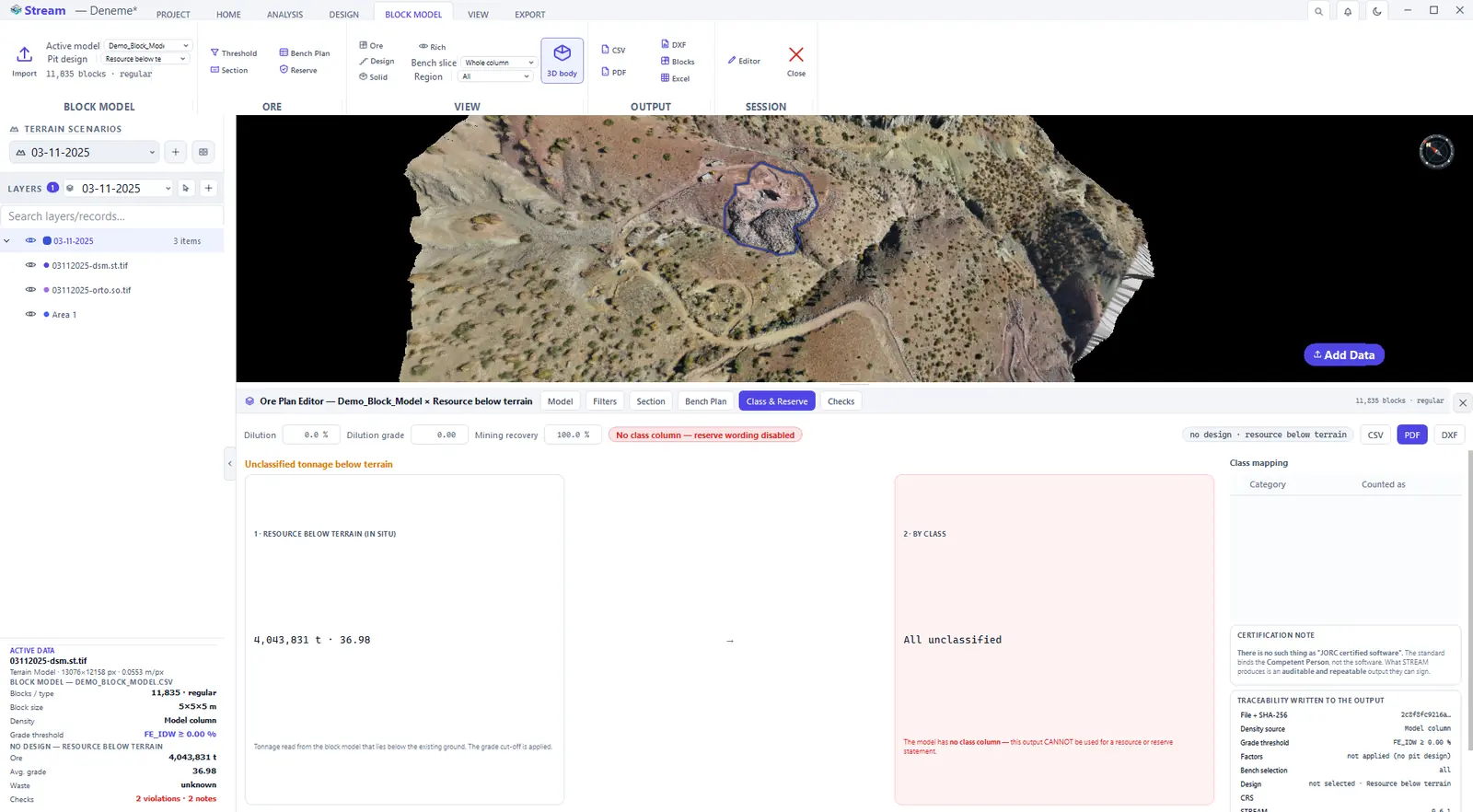
- Class & Reserve — you map the resource class column onto Measured + Indicated and Inferred; without a class column the panel says so and no reserve wording is written.
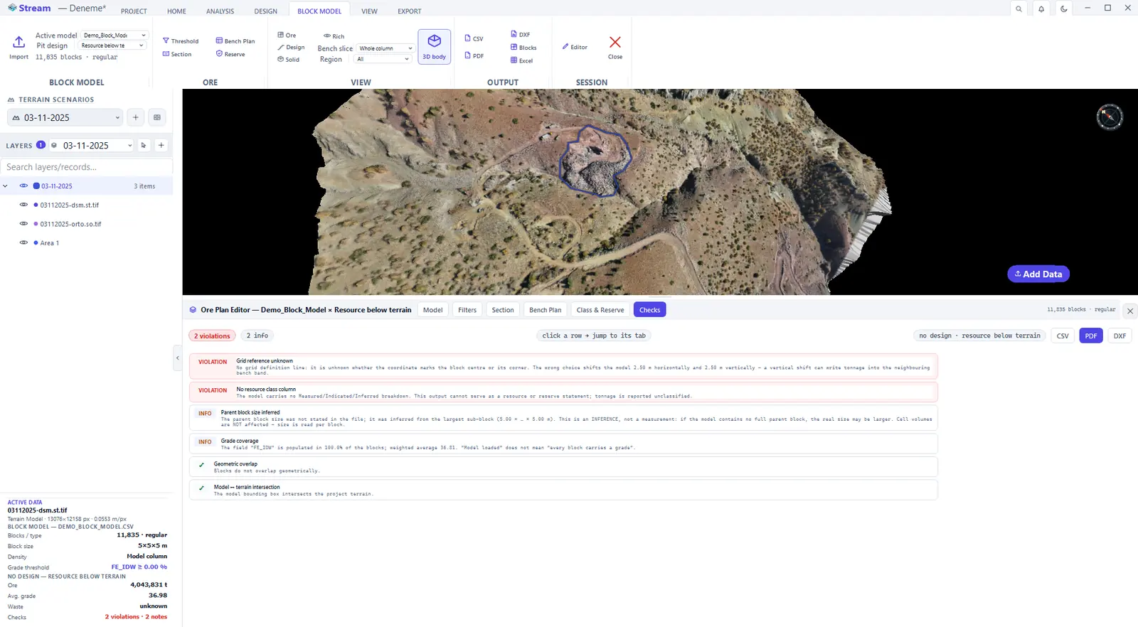
- Checks — validation findings (a grid reference that is unknown, a missing class column, geometric overlap, blocks outside the grid definition…); the tab title carries the count.
See the model on the terrain
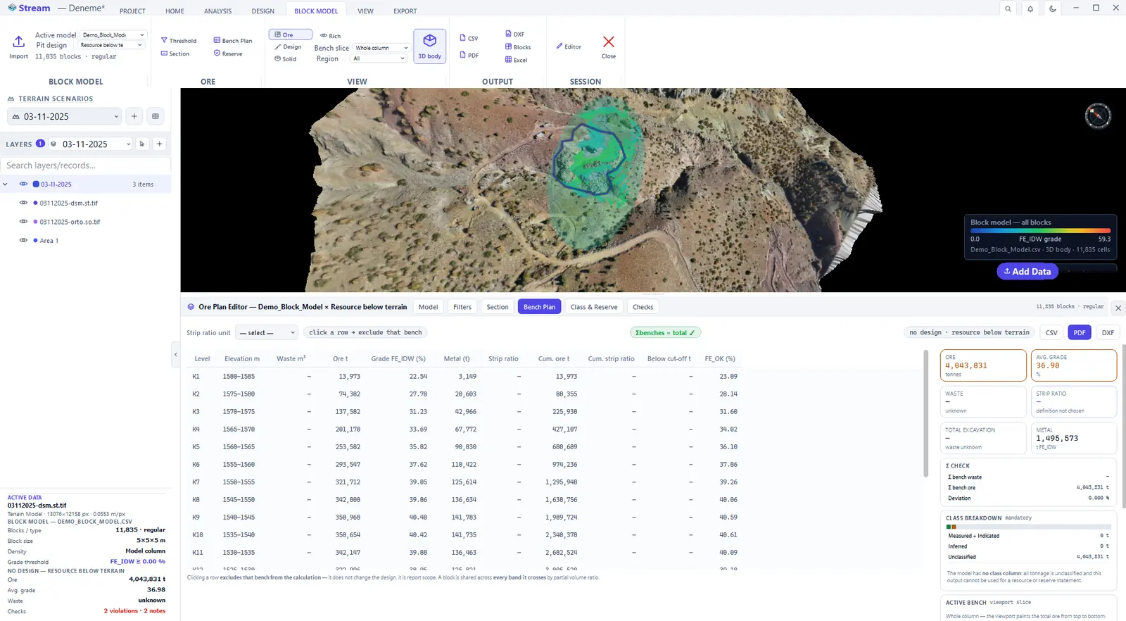
The VIEW group brings the deposit into the scene: in plan shading it is painted onto the terrain (the colour is the tonnage inside the pit in that column), in 3D body mode it is drawn in space, and Solid removes the transparency. Bench slice shows a single bench band.
Block Model view on the terrain.
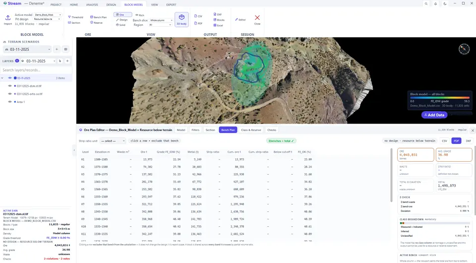
3D body view on the terrain.
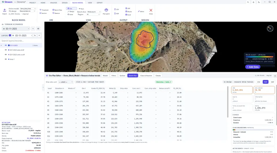
Solid blocks view on the terrain.
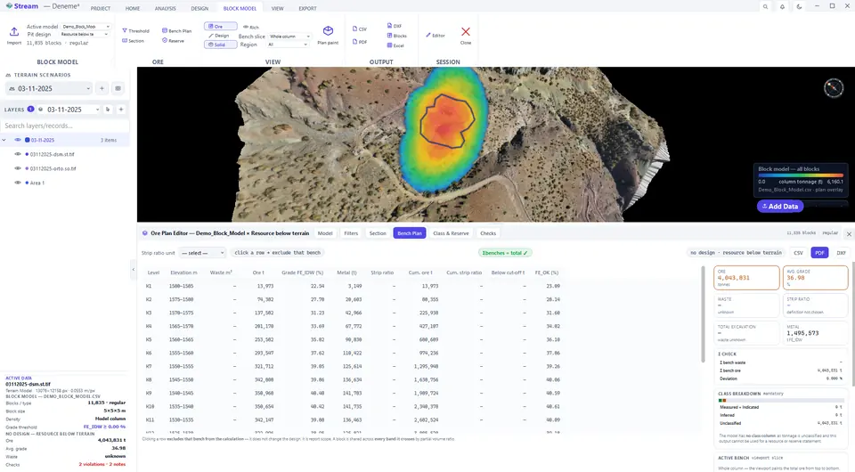
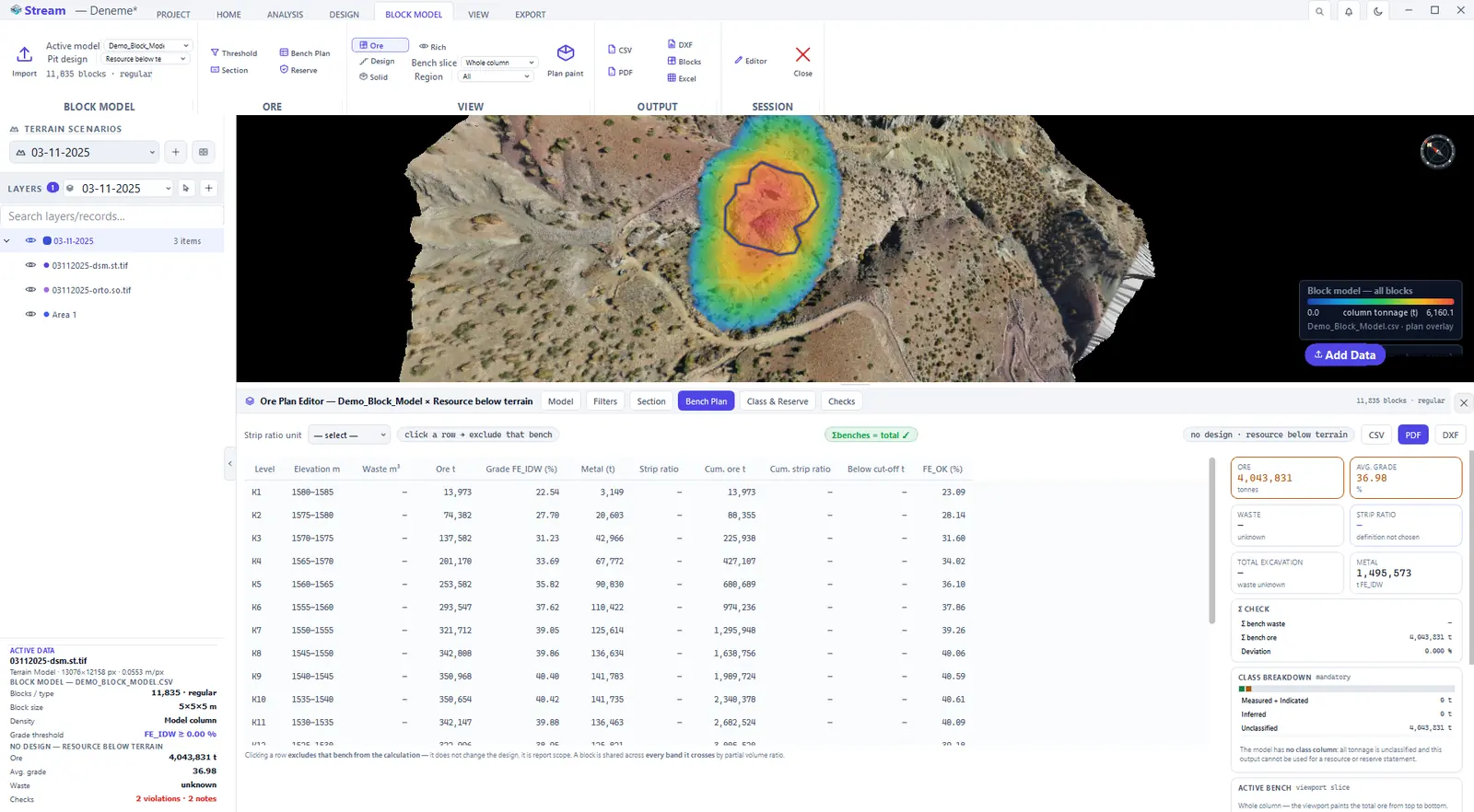
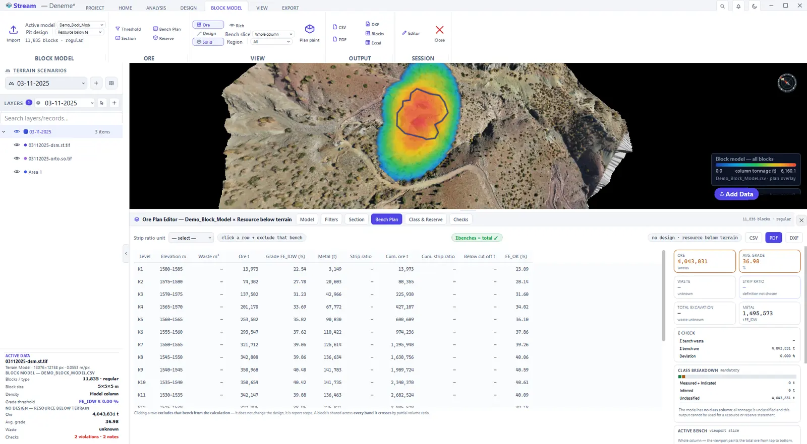
Without a pit design the module does not stay empty: the bench plan, the filter cards and the class breakdown report the resource below the existing ground, and the word reserve does not appear in the output. As soon as you select a pit design in the slope and platform editor, the same tabs switch to that pit. Output goes to CSV, Excel, PDF, DXF and Blocks (a row-by-row dump of the blocks that passed the filters).
Design a blast pattern
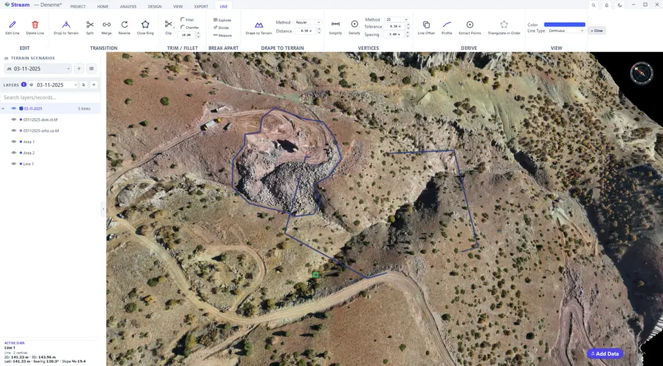
Open it from DESIGN ▸ BENCH ▸ Blast Pattern. Outline the block on a surveyed bench as an area, draw the face line along the crest, pick both in the editor and generate the holes.
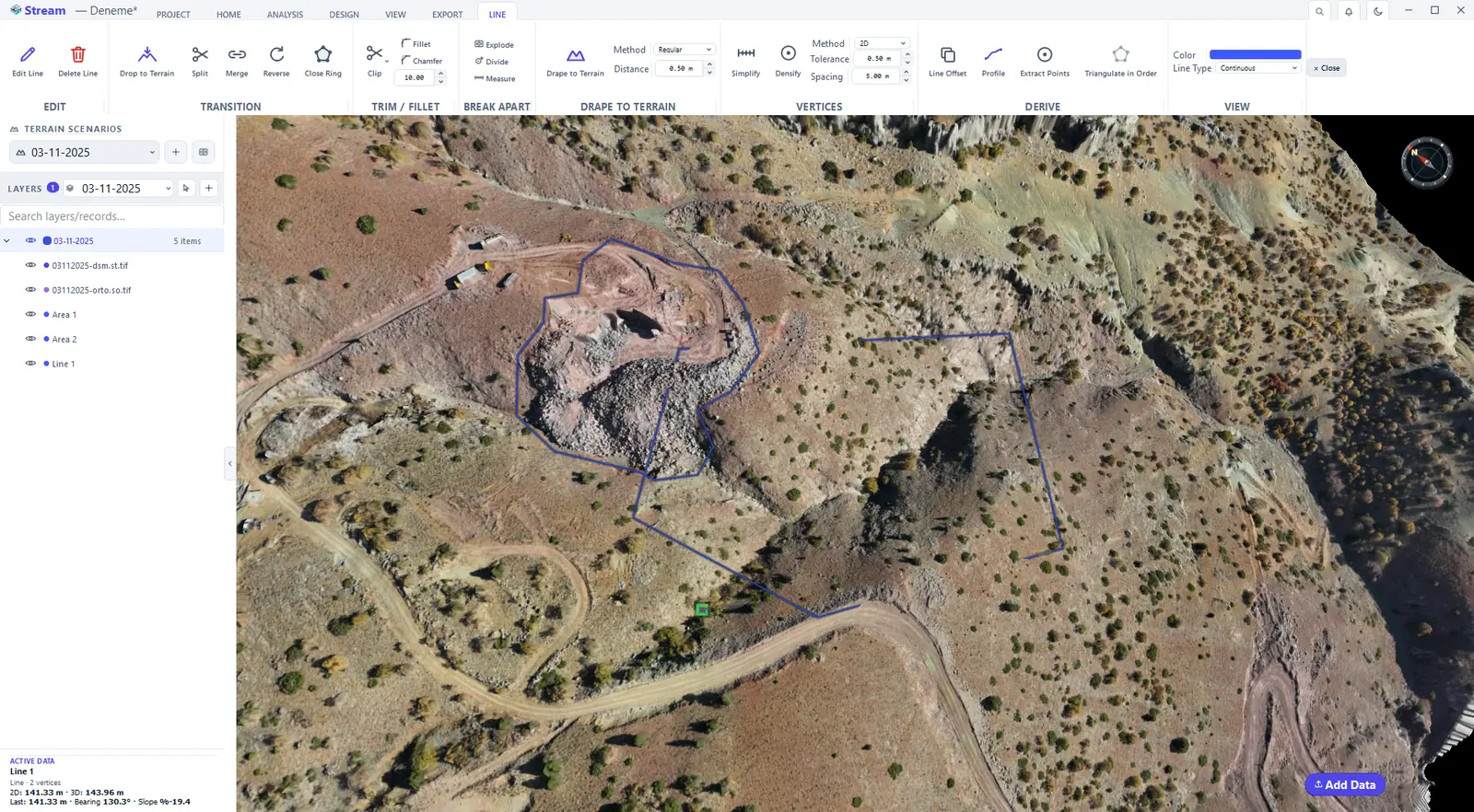
Draw the bench boundary and the free face line.
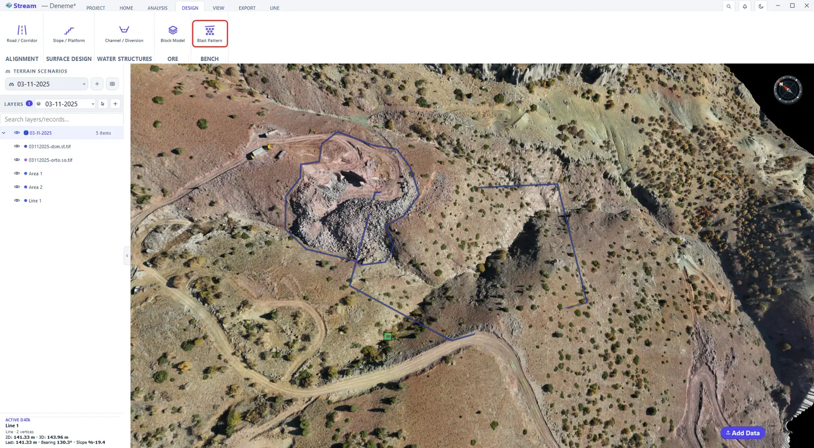
Open Blast Pattern on the Design tab.
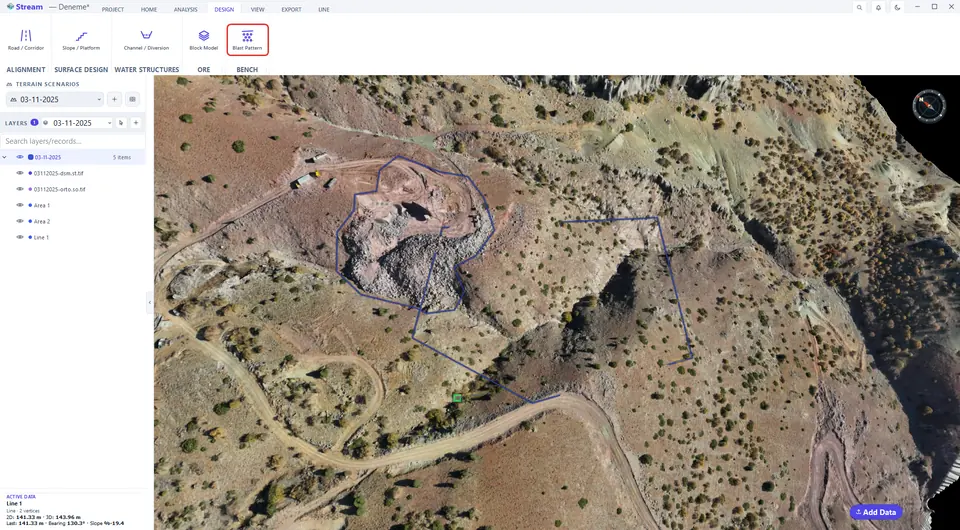
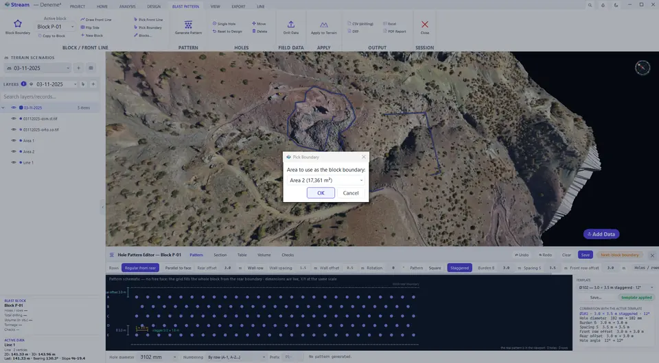
Press Pick Boundary.
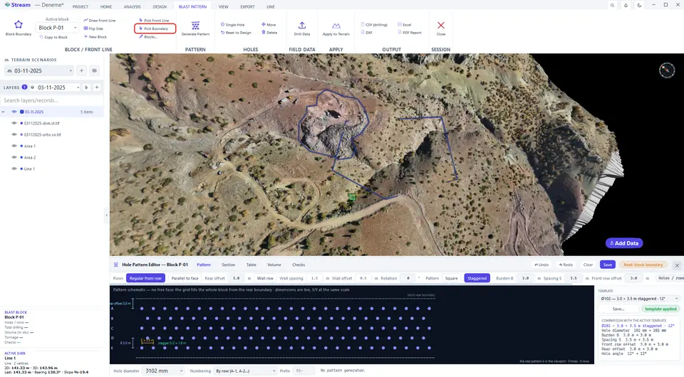
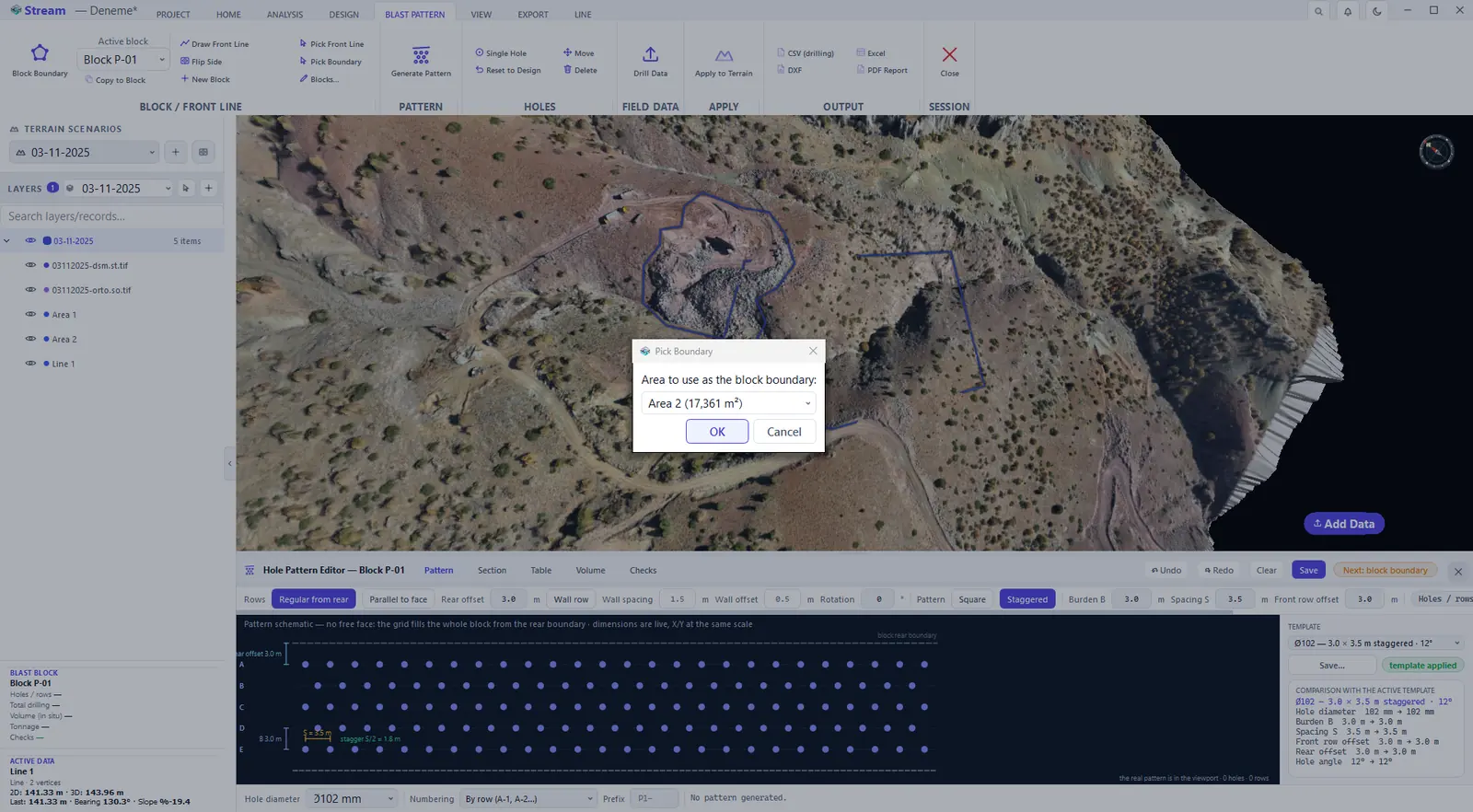
Press Pick Boundary - pick from the list.
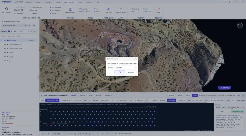
Press Pick Front Line.
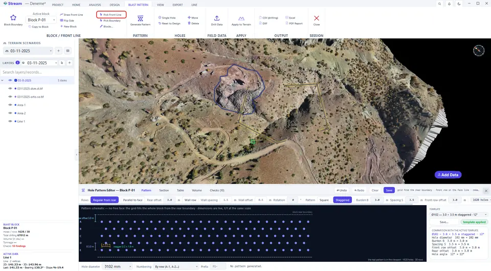
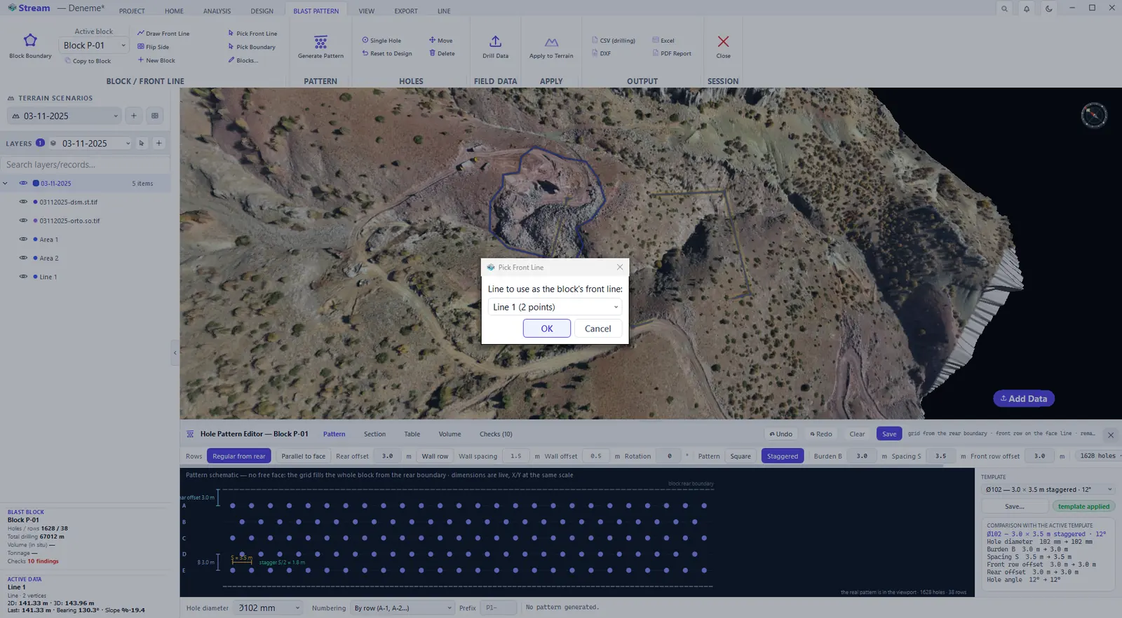
Press Pick Front Line - pick from the list.
Press Generate Pattern.
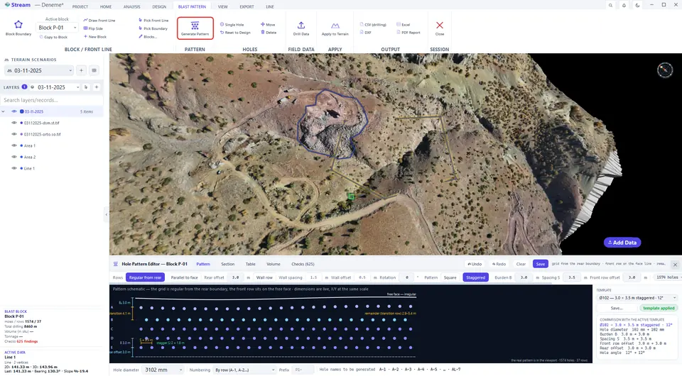
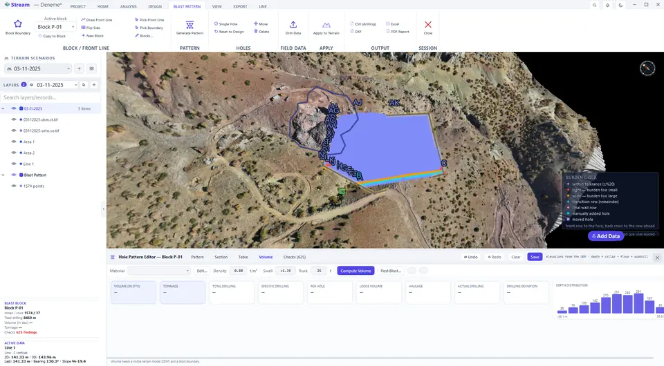
Drill holes are laid out inside the block; the Pattern tab holds the layout settings.
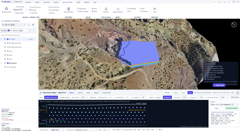
Section tab.
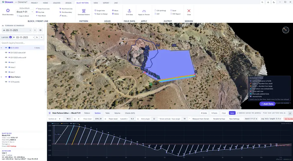
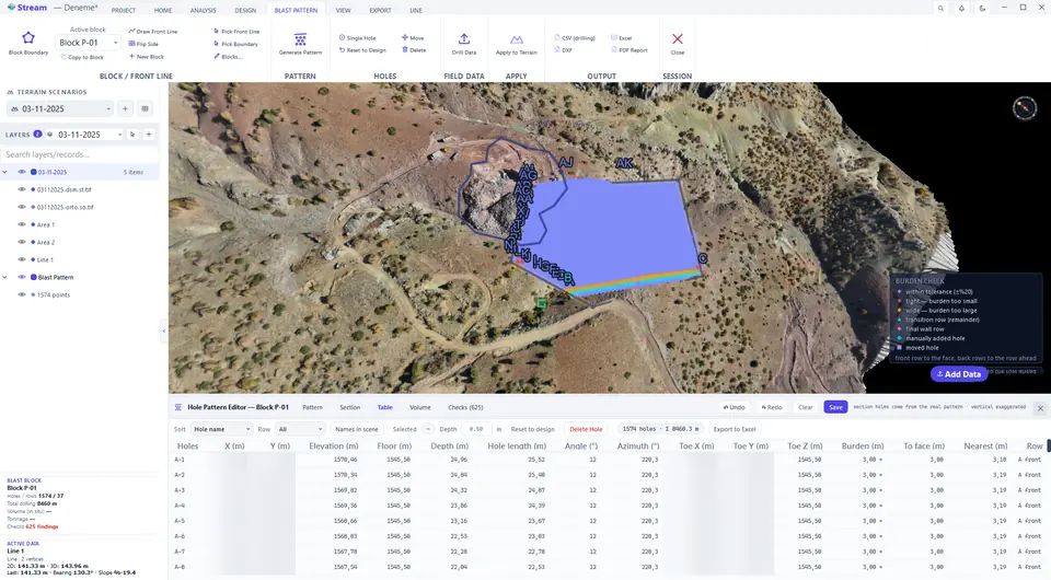
Table tab.
Volume tab.
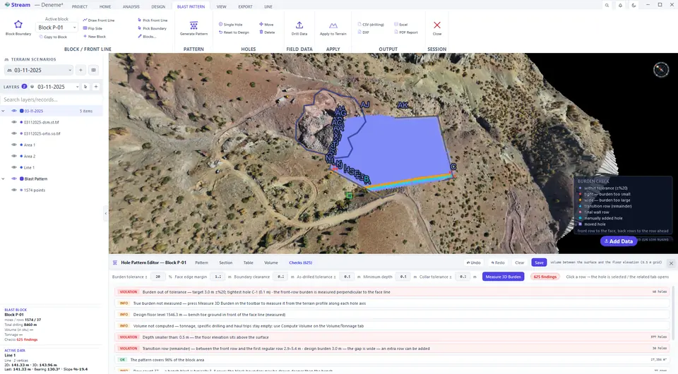
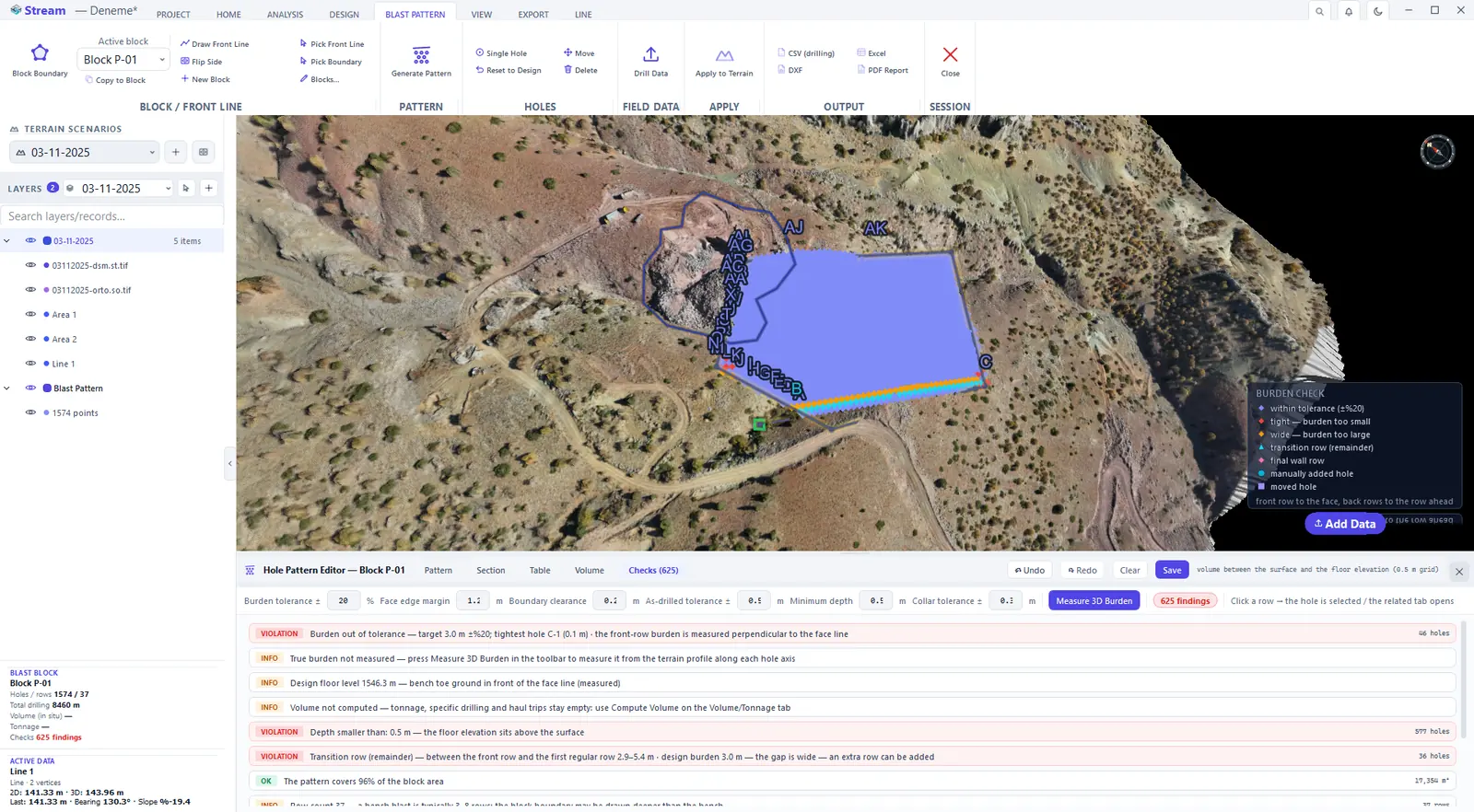
Checks tab.
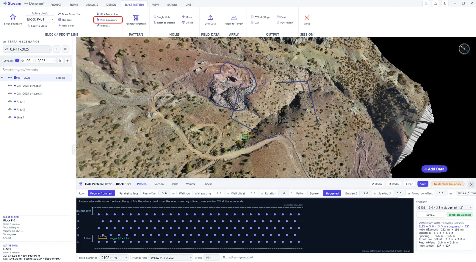
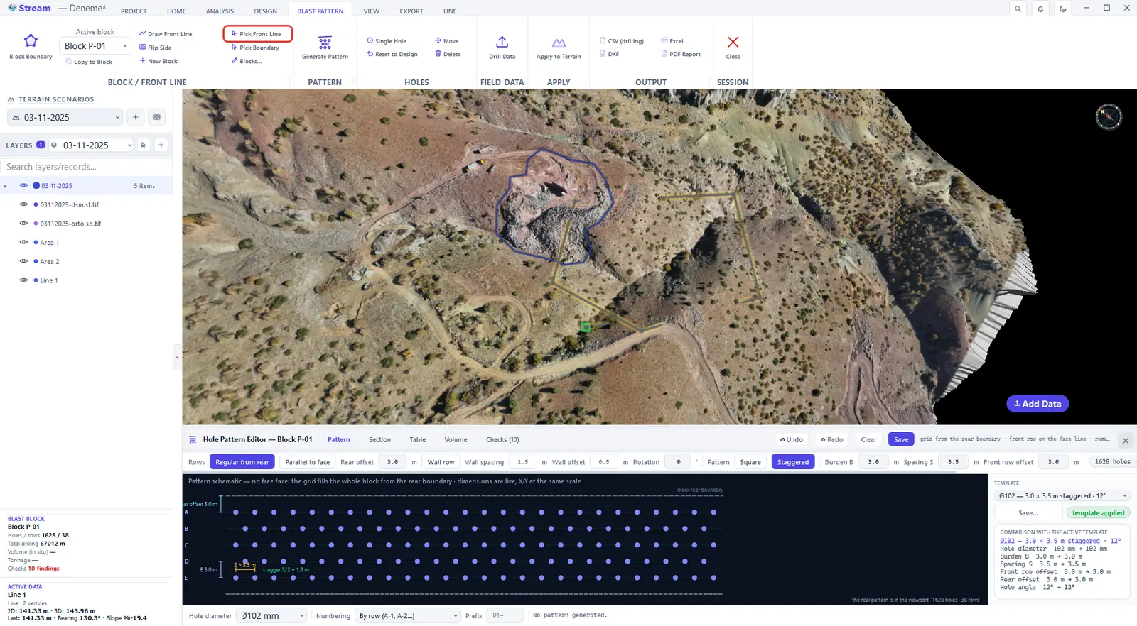
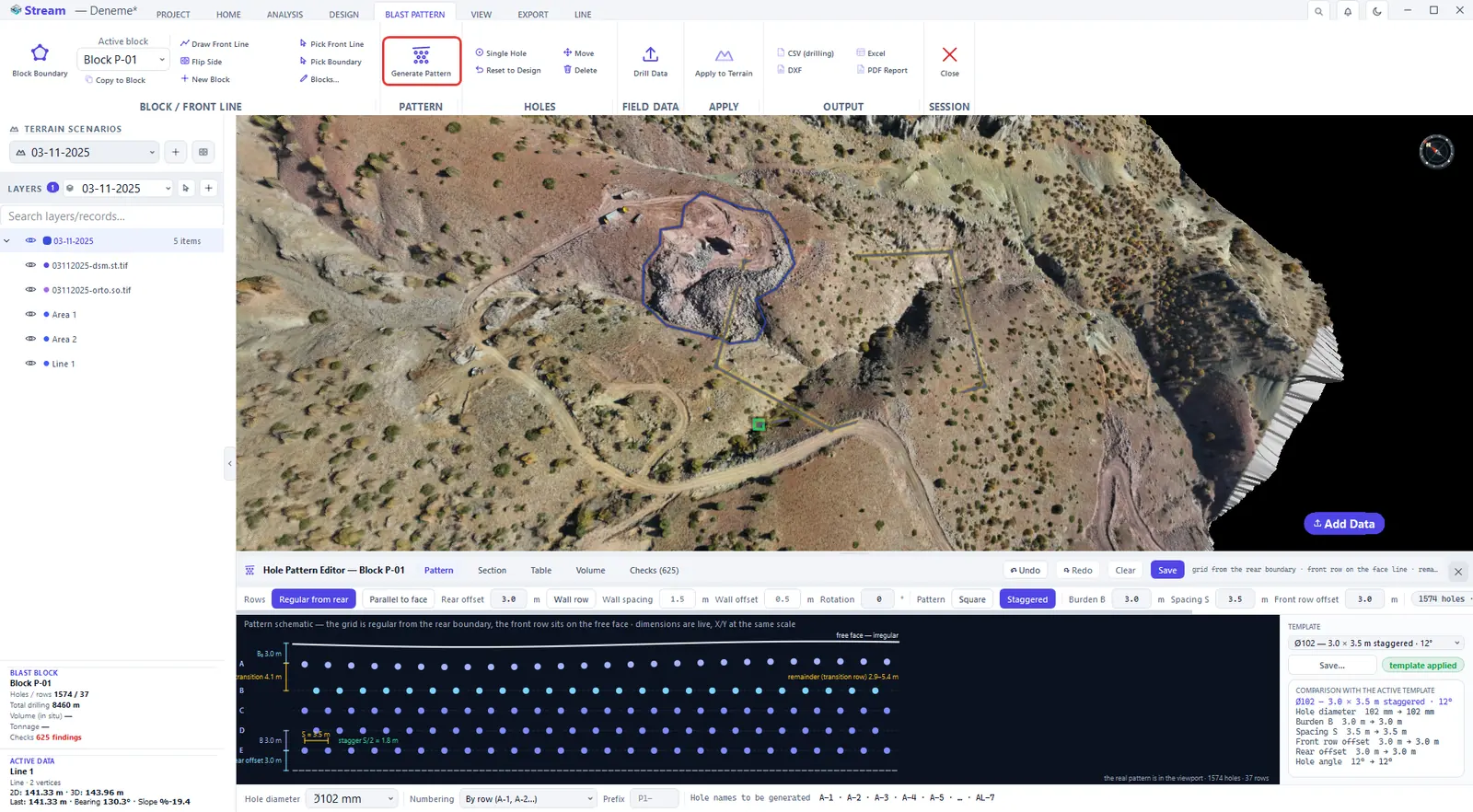
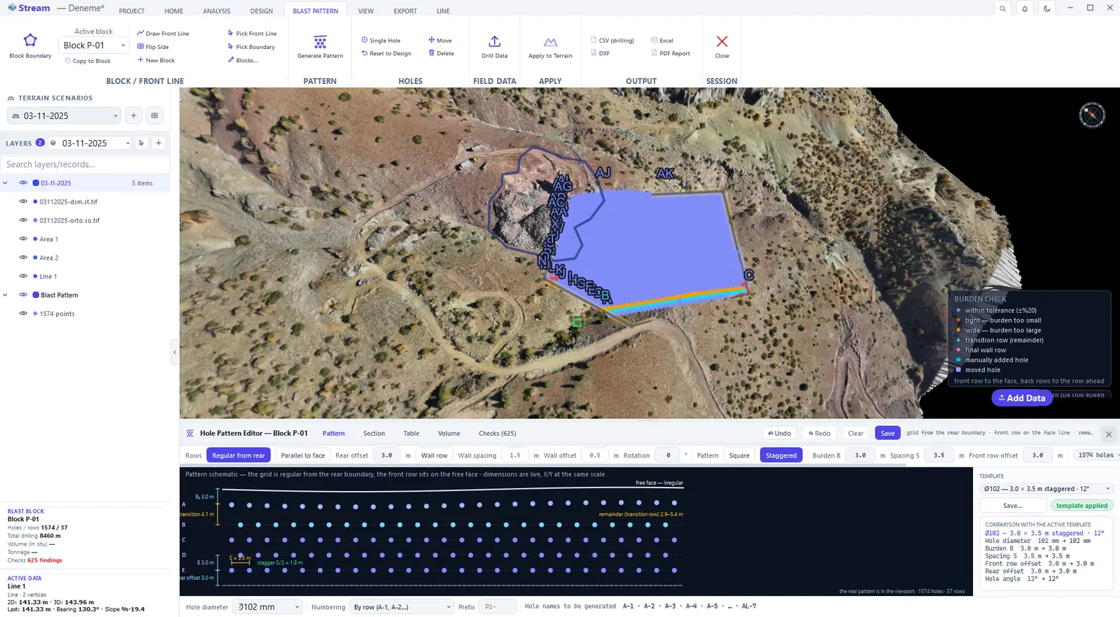
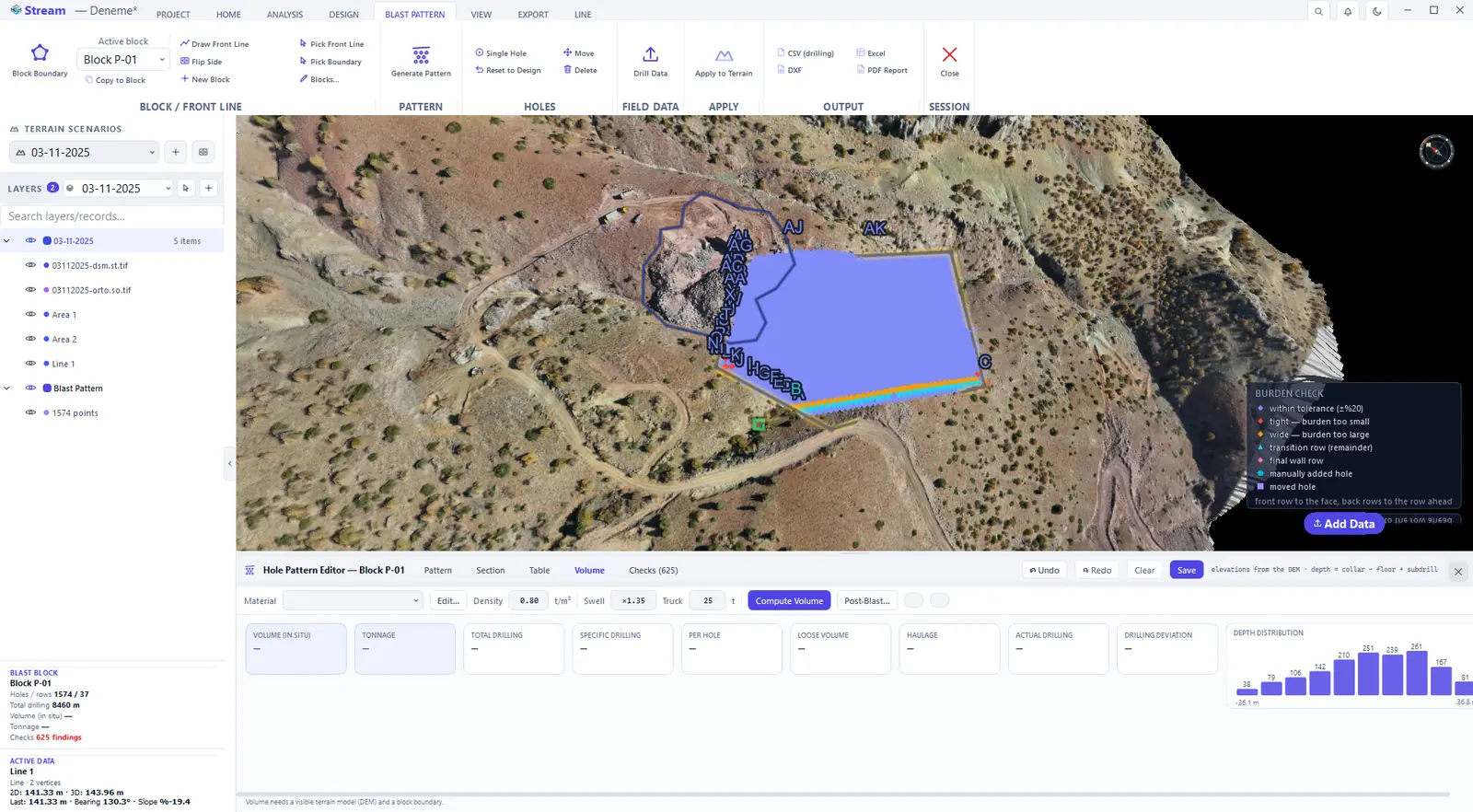
- Pattern — square or staggered layout; burden, spacing, front-row offset and grid rotation. The row nearest the face follows the face line rather than the grid, so the front burden stays even along an irregular crest.
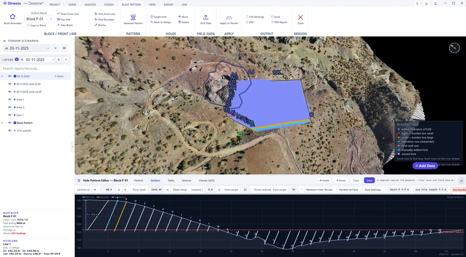
- Depths from the terrain — each collar elevation is read from the terrain, so hole depth and inclined length follow the real bench; add the subdrill and the hole angle.
- Section — the bench section through the holes.
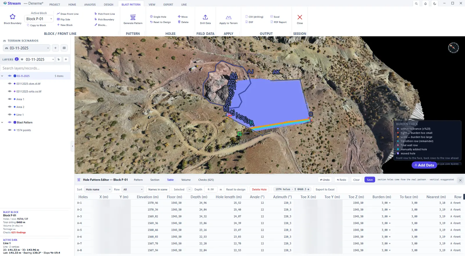
- Table — the hole-by-hole table with collar, depth and length; export it to Excel or CSV.
- Volume — the blasted volume and tonnage for the block.
- Checks — holes too close to the block edge, depth or burden outside the range you set and the other geometric conditions are flagged with the value and the limit before anything is drilled.
The pattern plan and bench section export to DXF and the report to PDF.
Next: Export and reports.
Related features
What each capability does, which formats it reads and writes, and answers to common questions: