Channel and diversion design step by step
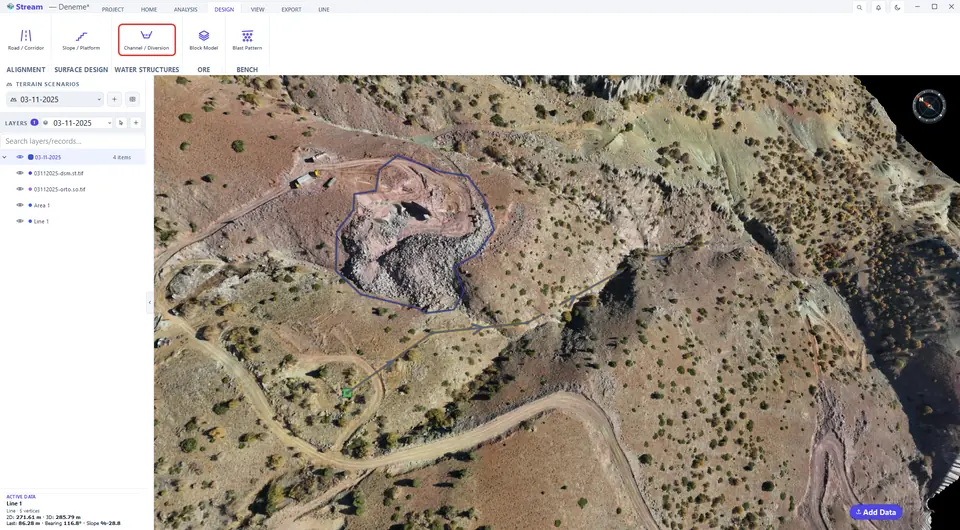
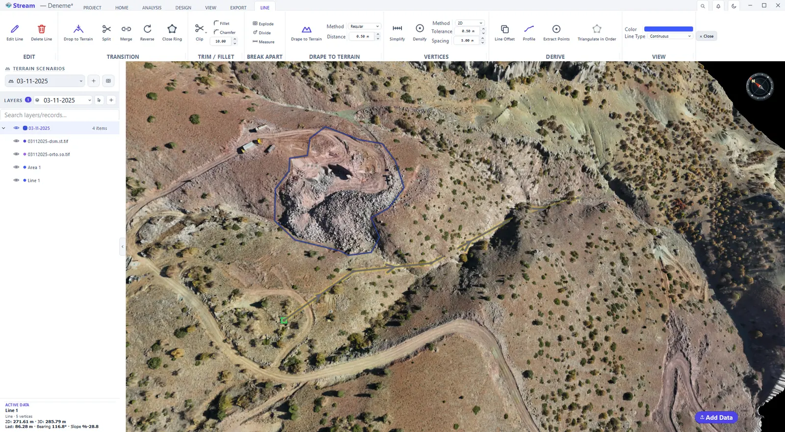
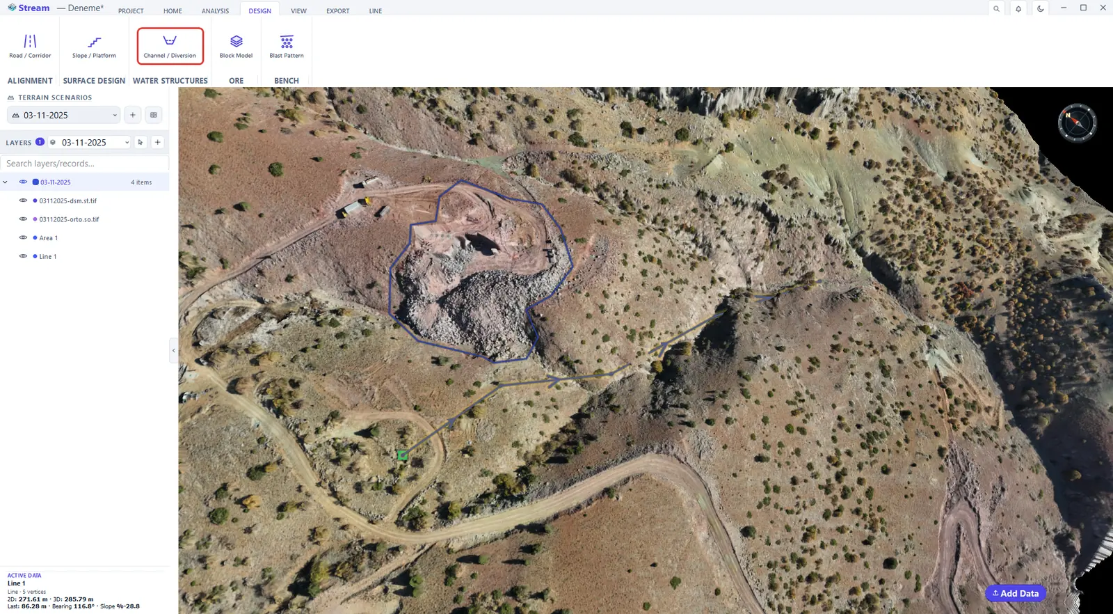
Open it from DESIGN ▸ WATER STRUCTURES ▸ Channel / Diversion. Draw the alignment, or turn an existing line into the channel axis with Pick Line.
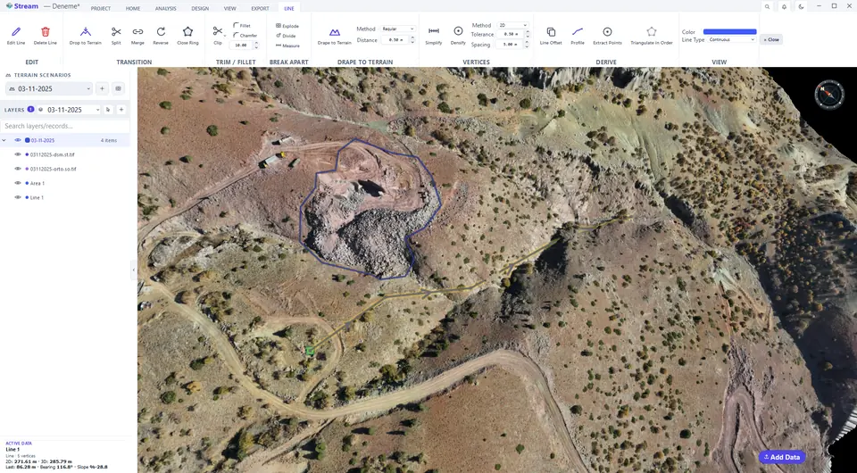
Draw the channel route.
Open Channel / Diversion on the Design tab.
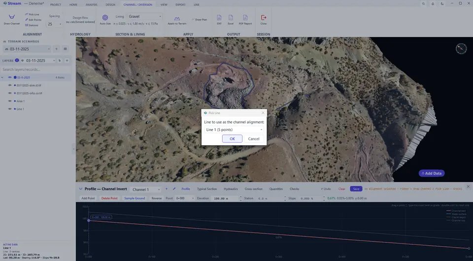
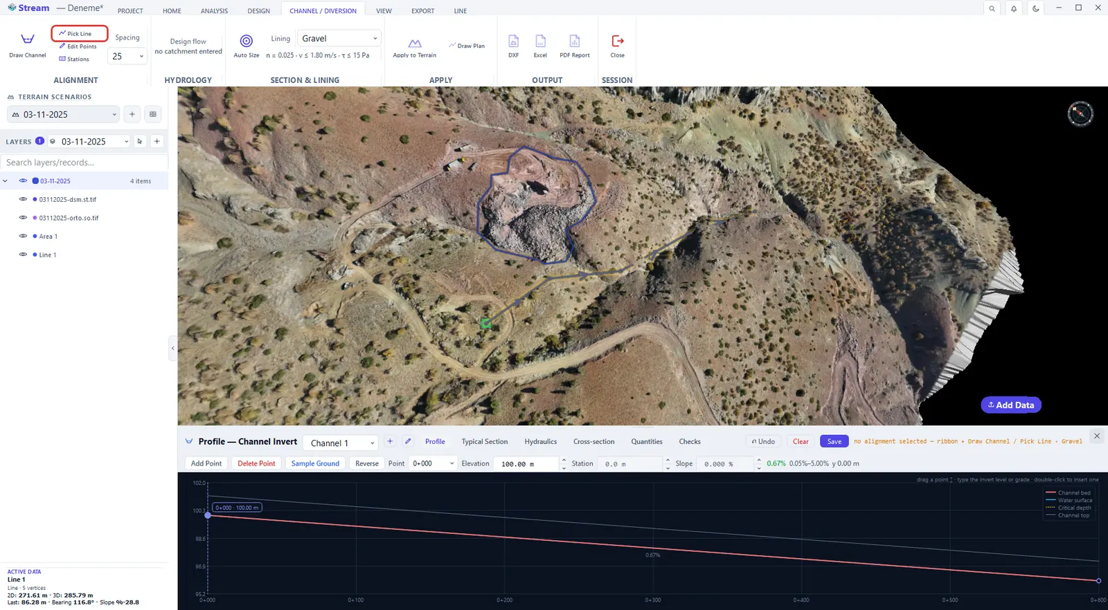
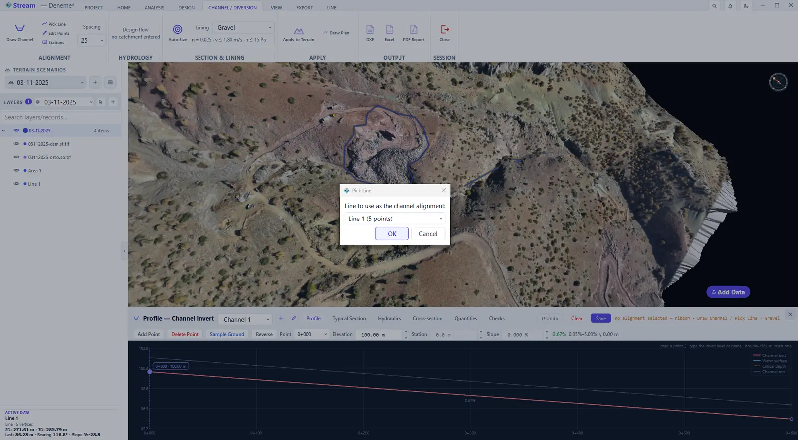
Press Pick Line.
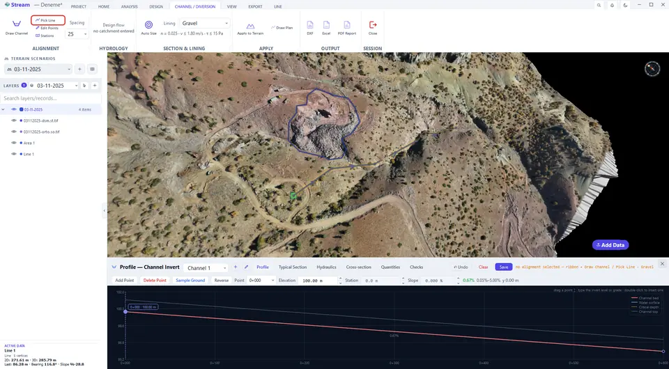
Press Pick Line - pick from the list.
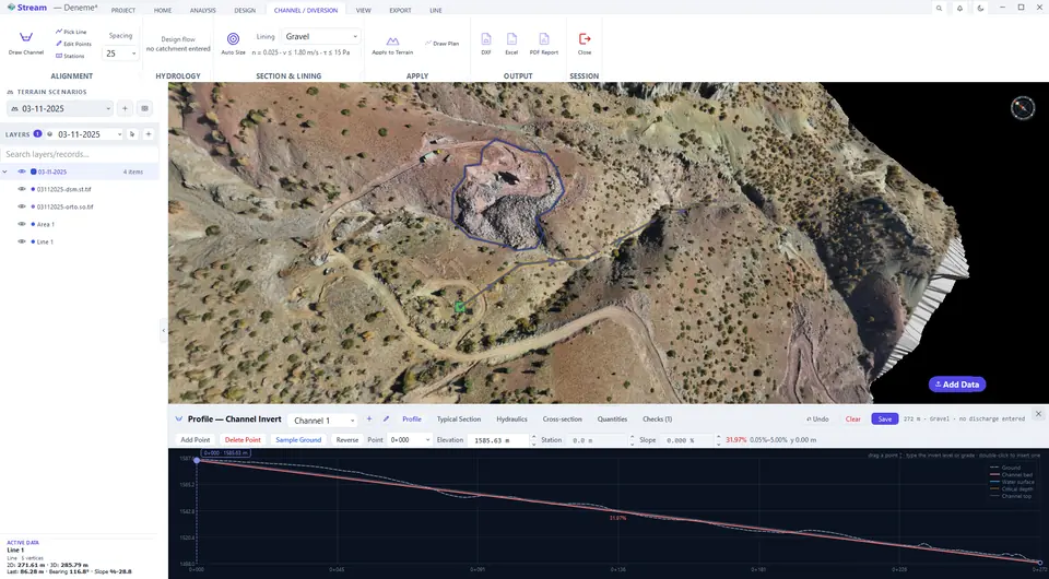
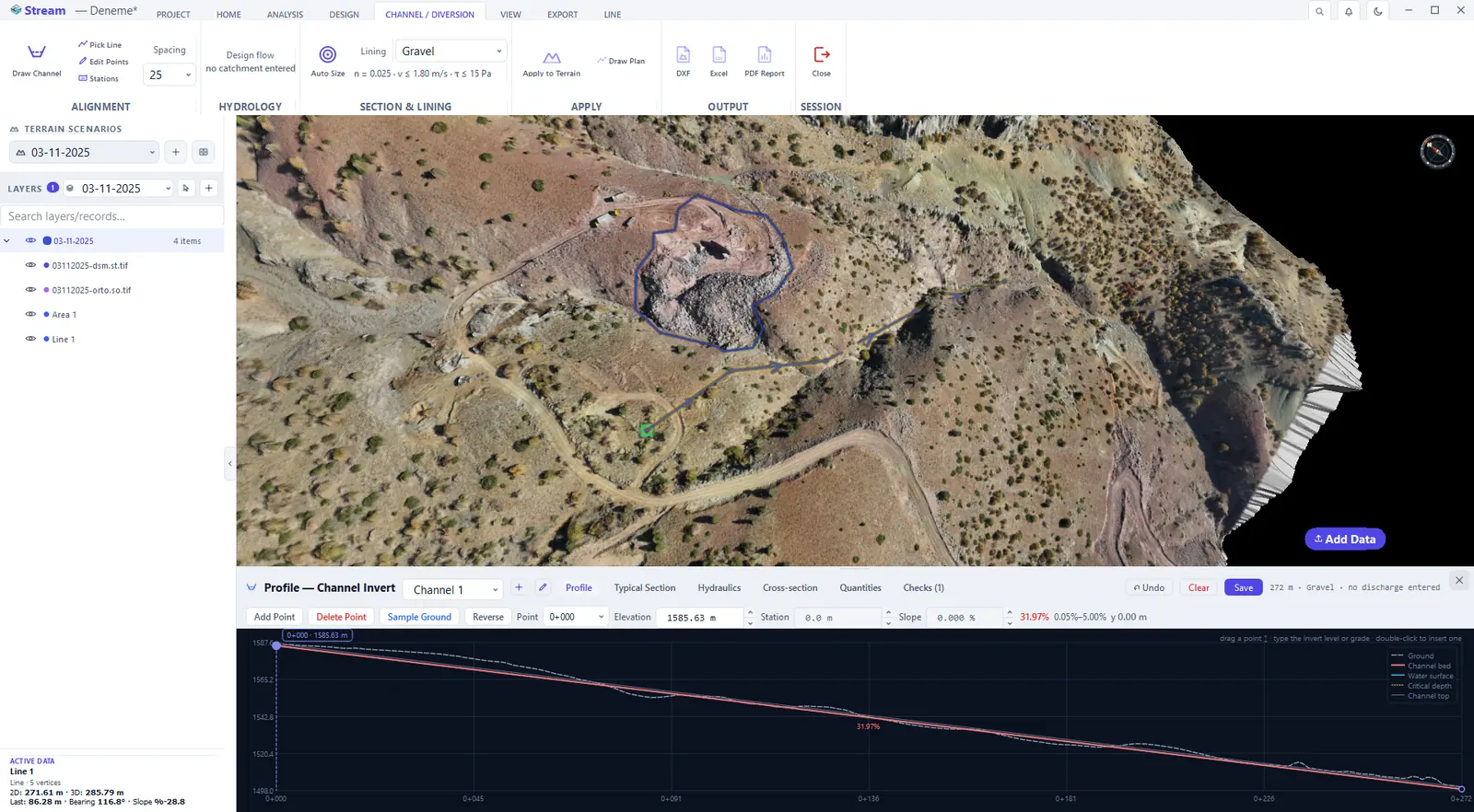
The Profile tab shows the channel invert sampled along the route.
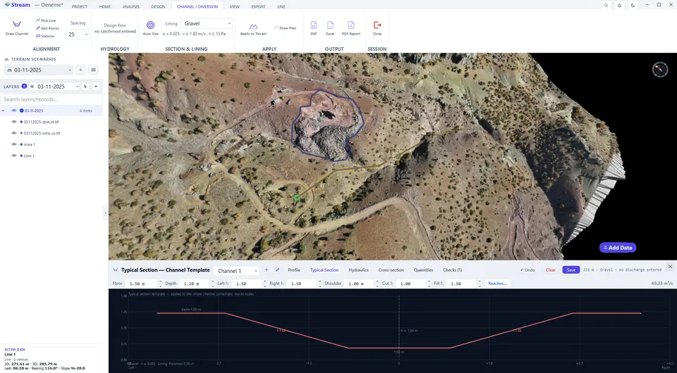
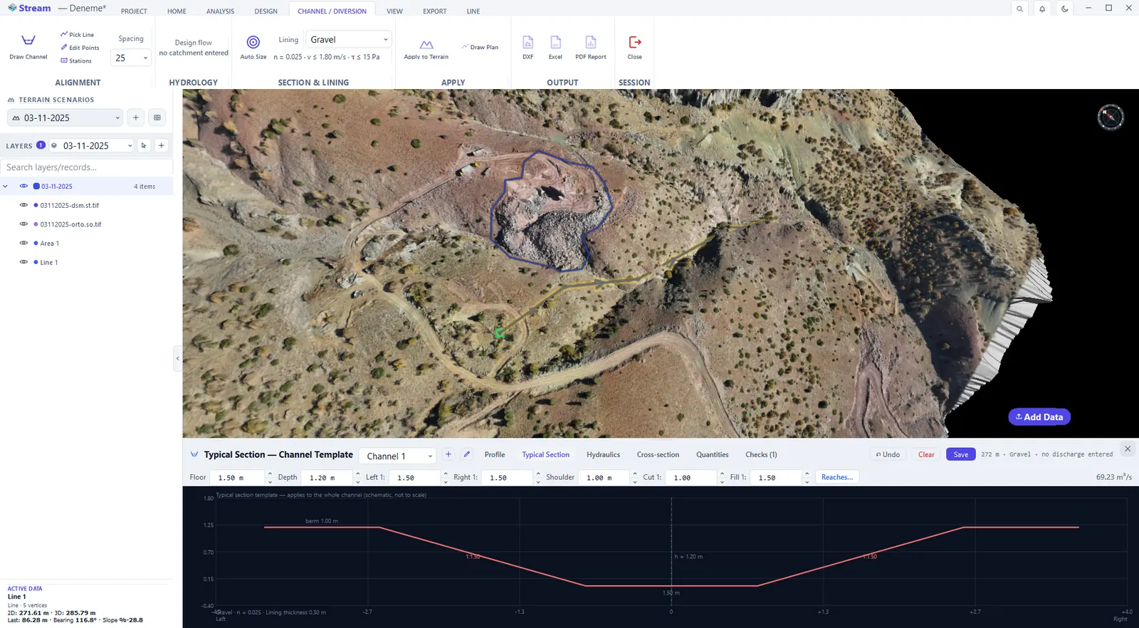
Typical Section tab.
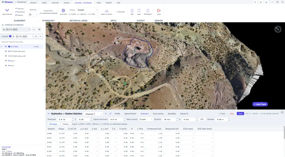
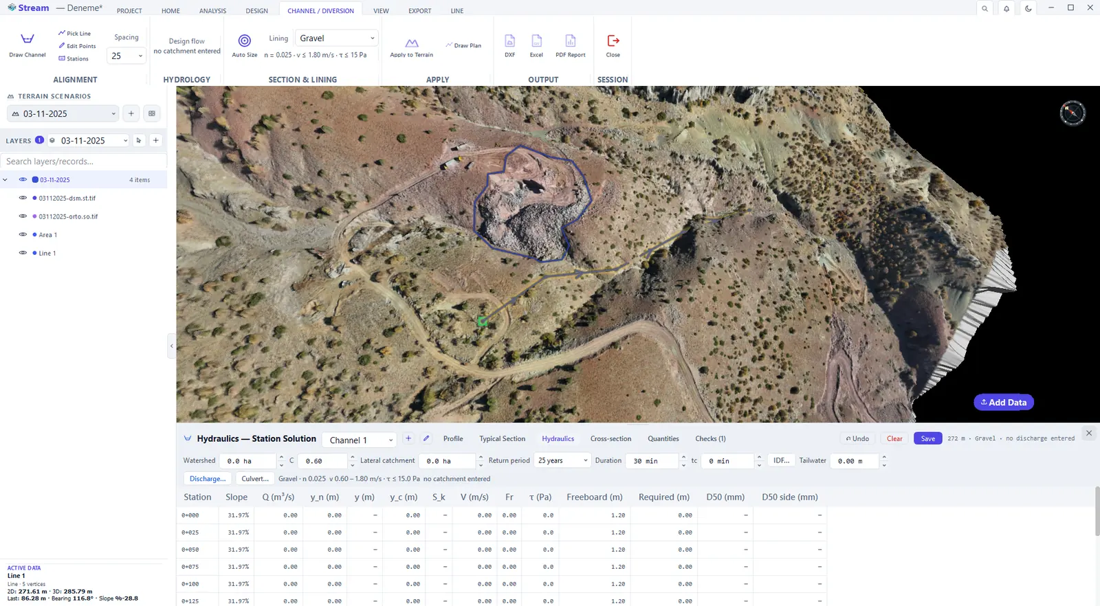
Hydraulics tab.
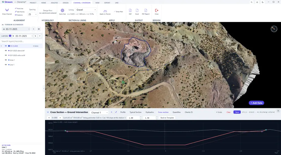
Cross-section tab.
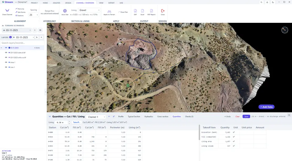
Quantities tab.
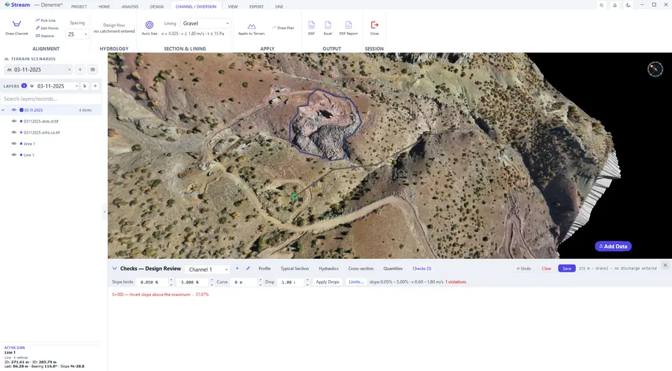
Checks tab.
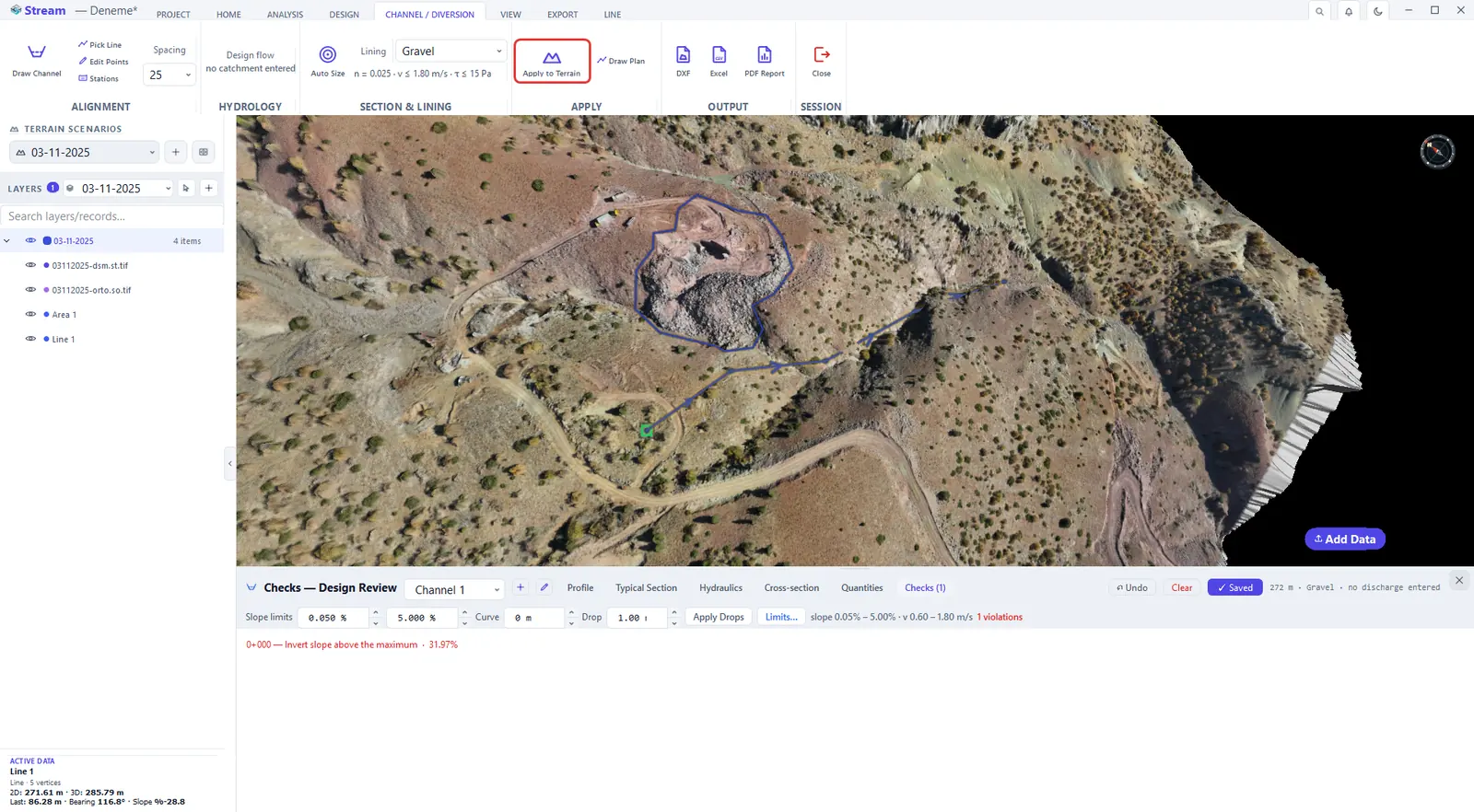
Press Apply to Terrain.
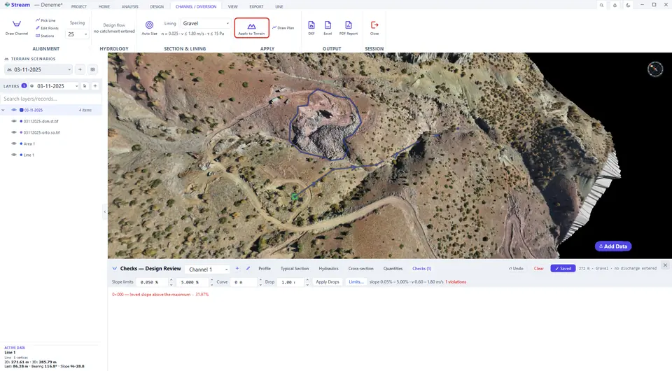
The design is cut into the terrain.
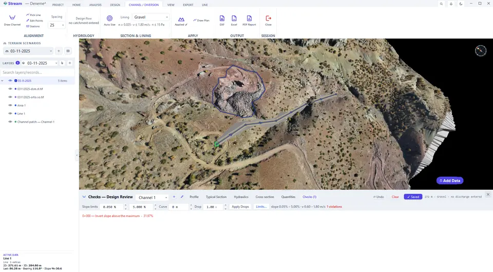
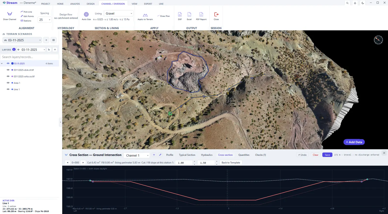
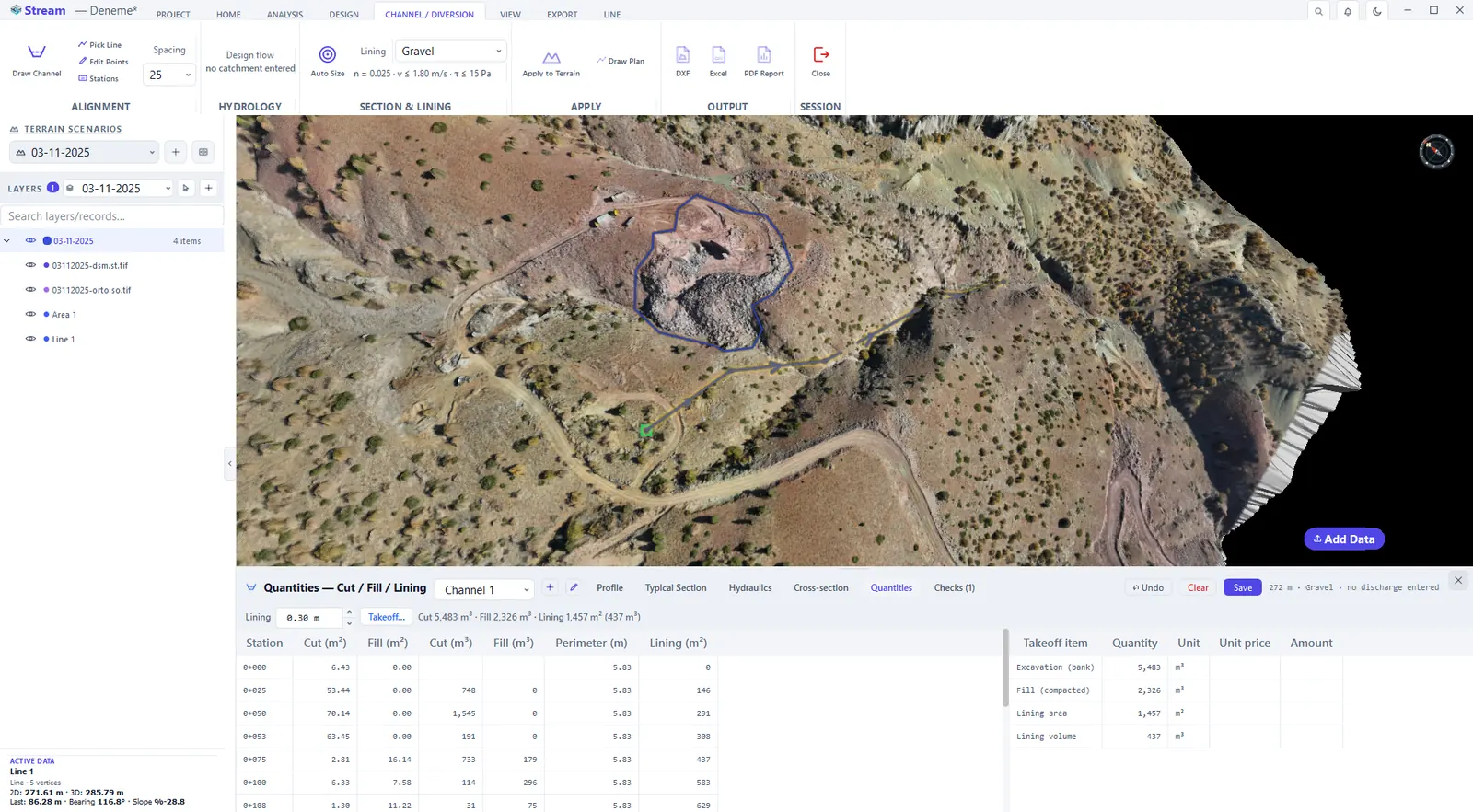
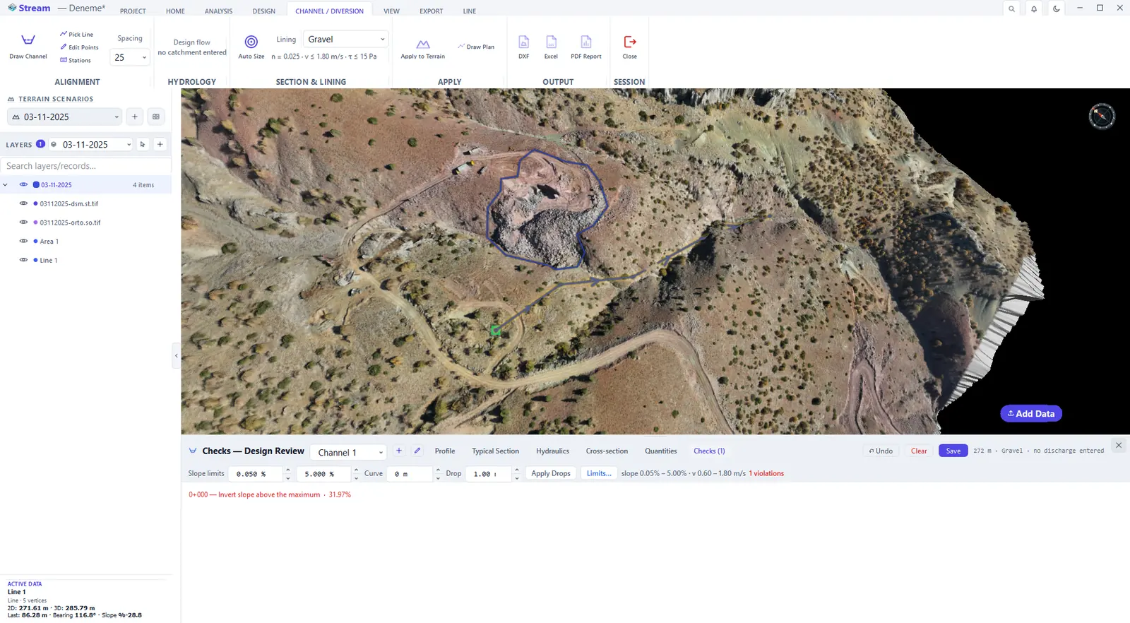
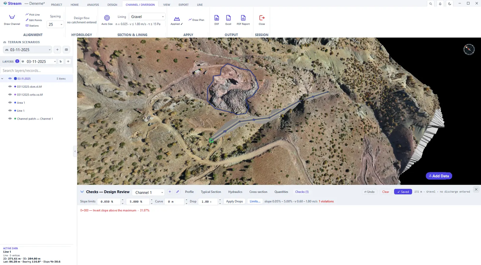
The editor has six tabs:
- Profile — the invert: ground elevation, bed elevation and grades at each station.
- Typical Section — bed width, depth, left and right batter slopes and the lining type.
- Hydraulics — normal depth, velocity, critical depth and Froude number at every station (Manning). The discharge comes from the rational method — catchment area, runoff coefficient, return period and storm duration — or from a value you enter.
- Cross-section — where the channel meets the ground, with its cut and fill areas (m²).
- Quantities — excavation, fill and lining amounts.
- Checks — the design review; the tab title carries the violation count. It reviews freeboard, flow regime, siltation below the threshold, the velocity and shear stress the lining permits, and adverse or level bed grades. If the hydraulics schedule is all dashes, the invert grade is adverse or level: a uniform-flow solution needs a positive grade, and Reverse on the long profile swaps the head and the outlet.
Apply to Terrain cuts the channel into the ground; if you change the design afterwards the patch is marked stale and Re-apply refreshes it. Plan, profile and cross-sections export to DXF, the tables to Excel and the design report to PDF.
Related features
What each capability does, which formats it reads and writes, and answers to common questions: